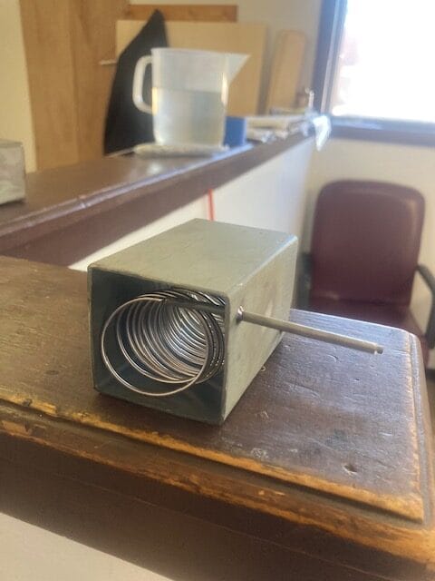
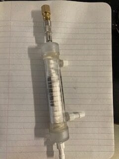
We occasionally make hydrogen stripper systems where the goal is to strip the hydrogen, and sometimes other gases from a mixed gas leaving everything else in place. We use metal membranes, coiled as shown below, if the gas to be removed is hydrogen. For other gases H2S, siloxanes, we use polymeric membranes. In either case, it’s not a product we advertise, but it’s worthy of a blog post.
A typical customer was a Cambridge researcher using gas chromatography with hydrogen as the carrier gas to separate a series of compounds. He now wanted to recover the separated compounds without the hydrogen.
A hydrogen extractor during manufacture.
To minimize the amount of membrane needed, I like to create a plug flow. If the flow is low, or there isn’t much hydrogen, we use a single coiled membrane. If the flow is high or there is a lot of hydrogen, we use several straight membranes in parallel, typically with baffles; we even have a patient for this. Some customers want to recover the hydrogen. If so, we extract it with a vacuum pump. Other customers just want the hydrogen gone. For these oxidation works well. The reaction H2 + 1/2 O2 –> H2O is essentially irreversible, and quite fast on a palladium surface.
A basic analysis is to assume that flux is proportional to hydrogen pressure in the gas, and calculate the hydrogen pressure as total pressure, P, times the fraction of hydrogen in the mixed gas, H/(H + inerts) .
Then, for any small amount of membrane area, dA, the small amount of hydrogen removed per second, dH equals the area, dA, times the permeance of the membrane, P, times P, times H/(H + inerts): dH = -PP (H/(H+Inerts)) dA.
We now rearrange the above: dH(H+Inerts)/H = -PP dA, and integrate:
∫ dH ( H+Inerts)/H = ∫(1 + inerts/H) dH = ∫ -PP dA. It’s found that
Hi – Hf , + inerts • ln (Hi)/(Hf) = PPA. Thus,
A = (Hi – Hf )/PP + (Inerts/PP) ln (Hi)/(Hf).
where A is the total area of membrane needed, inerts = the inert gas flow per second, and and Hi and Hf ate the hydrogen flow rates in the mix at the beginning and end of the extraction. Hi – Hf equals the total amount of hydrogen removed per second.
Note that the first term dominates in the beginning of the extraction process, or where there is a lot of hydrogen content, ln 1 =0), and the pressure of hydrogen is essentially P. The logarithmic term dominates in latter (final) stages, where the inert content is the majority and hydrogen content changes fast. In these later stages, very little hydrogen removal decreases the partial pressure by half, but a significant area of membrane is needed to remove every successive 50% since the hydrogen pressure is continuously decreasing by 50%.
You can derive similar equations for normal distillation, as used to make liquor or refine gasoline. You can also modify the above expression because permeation isn’t always proportional to pressure but to the difference of Pressure to some power, the 1/2 power, or so. I should also mention that, in membrane distillation and liquor it is important to continuously remove components that can build up in the still. For membrane- based hydrogen stripping, we do this using a back-pressure controller, or a flow controller. Thus, if you know you have a feed of 95% hydrogen, 5% desirable inerts, you want a to maintain a suitable back-pressure and you want a flow controller that lets mostly inerts out of the process with minimal H2.
She was only the moonshiner’s daughter, but he lover her still.
I’ve come to discover that we have a major helium shortage. Helium is used in semiconductor manufacture, in MRIs, chemical chromatography, and low temperature refrigeration. I need it for leak checking, something we just started doing, a quality assurance test for our products and now a service. I’m not hit hard by the shortage, but some other industries are.
For gas chromatography, helium can be replaced by hydrogen, as discussed here. I was recently invited to a seminar on it. Hydrogen gives sharper peaks than helium, and slightly quicker residence times, but it has to be very pure. As it happens, We make hydrogen purifiers at REB Research, it’s our main product. These purifiers allow you to do chromatography, or brazing with low-cost, bottled hydrogen, and even with electrolysis hydrogen. The purifier is a one-time purchase, and then you can use low cost hydrogen. You will want to vent the output of the chromatograph; you use very little for chromatography, or brazing, ~50 cc/min typically, but without some venting, it can build up eventually.
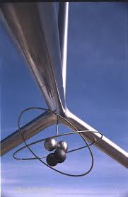
Helium monument Amarillo
Some testers have begun using natural gas for leak checking, I notice. It’s not a sensitive, and you have to make sure you’re vented so there isn’t a flame. A safer alternative is forming gas: 5% hydrogen in nitrogen. The leak sensitivity is low, well below that with helium, but above smoke, or smelly compounds.
A major cause of the helium draught is Biden’s sale, with congressional approval, June 24, 2024 of the Federal Helium Reserve. This was a massive underground stockpile of helium, 32 billion cubic feet, that filled a set of caverns that span three states. We’d managed the stockpile for years, with a monument too, see right, but Biden sold the entire reserve including 425 miles of piping, purifiers, and caverns to Messer LLC, a German company owned in China. See an NBC article about the sale, here. The price was $460 million, less than 1¢ per cubic foot of He, with the pipes, storage area, and purification facility thrown in for free. Messer LLC quickly sold off the helium to recoup their purchase, and now it’s gone.
The sale of the reserve would not have been so bad, but in March, the Iranian Revolutionary guard bombed Qatar’s Ras Laffan natural gas and helium plant, the world’s largest helium plant, doubling the spot price of helium, see. AP article here. Why does Iran, a Shia-Islamic republic, bomb plants in Qatar, another Shia Islamic republic? it’s a form of economic war. Russia is another major gas and helium producer, and I expect Ukraine will bomb Russia’s plants too. If you use helium for chromatography, you might want to switch to hydrogen, and invest in a purifier from REB Research.
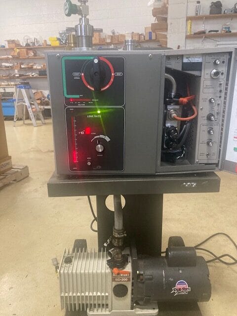
Our helium leak detector being calibrated with a standardized He leak
We just got a new helium leak detector, a Varian 938, about 15 years old, shown at right. Our old detector, a Veeco, had not worked well for years, and then we could no longer get it fixed. For a while we outsourced our leak checking, and on rush jobs it didn’t always get done. Now we can check everything in-house at much better sensitivity than before.
It used to be that helium leak checking services were common locally, in Detroit, but we lost a lot of manufacturing and our quality checkers left too, for Ohio, then abroad. Companies that used to do He leak checking switched to fluorescent die checking, which isn’t as good, and then stopped checking altogether. But small cracks at welds are not uncommon, particularly with laser welding of stainless steel. They form as the metal cools, and are too small to see. They show up in helium leakage through the micro-cracks, and if not detected and corrected, these cracks will grow and destroy a pipe or system over time. For my products, hydrogen purifiers, the micro cracks affect hydrogen purity. Any crack that helium can get through will allow impurities to diffuse into our output hydrogen. Because of the problems of micro-leaks and durability, it used to be obligatory in the nuclear navy to helium leak check every part.
The picture above was taken while calibrating our new helium leak detector. I’d bought some calibrated sources, in this case, one certified to bleed at 3.6×10⁻⁸ cc/sec, which is equivalent to 2.1 x 10⁻⁹ slpm. If a leak of that rate would appear in one of my 1 slpm purifiers, that would imply a delivered hydrogen purity of 99.999998%, and that’s generally the purity limit I certify. This is also a common leak standard in the industry, but my new detector is better than that standard. We can test down to 0.5×10⁻⁹cc/s . A 1 slpm purifier with that leak rate will deliver hydrogen at 99.9999999+ purity, more than nine-nines, as they say. On the calibration day, above, I tested three new purifiers, and found they were all perfect to the higher standard, ≤ 0.5×10⁻⁹cc/s. I’m so happy with this, I thinking of going into free-lance, helium leak checking. There’s no one local who does it.
In case you want to know, I bought this detector on eBay but found it didn’t work. I tried cleaning key parts, replaced the pump oil, nothing helped. Then bought another leak detector, with a spare filament, but without a pump or a mass-spec unit. It included the standard leaks that I now use to calibrate. That one didn’t work in the same way that the original one didn’t; we never reached pressure, and the filament never came on. Eventually, I came to believe that the vacuum pump was a fault. I sent it to a great pump repair shop in Greentown, PA, and discovered they also repair helium leak detectors. I hope to visit them. They replaced the pump and spiffed up my detector at a decent prices ($1500 as I recall). Now, it works like a charm.
Generally, when you make hydrogen, you make wet hydrogen, hydrogen contaminated with water. Usually you want to dry the hydrogen before you use it or compress it. if you compress the hydrogen for transport or storage without drying it, the water will condense and perhaps freeze, clogging valves and fittings.
Water contamination of hydrogen is also a problem for brazing. Hydrogen is a good, cover gas for brazing because of its high heat transfer properties and its reducing chemistry. When the hydrogen is contaminated with water vapor it is unstable for use with stainless steel and similar metals as it will cause oxidation of the surface, resulting in a grey-green surface, and preventing good brazing. Some other contaminates can be problems, e.g. CO2 but water is the main problem in brazing environments.
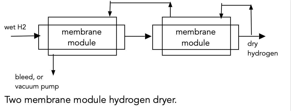
One more example where drying hydrogen is important, is for its use in high altitude balloons. At high altitudes, water can condense, changing the lift characteristics, and perhaps freezing and puncturing the balloon. For all these applications, I suggest use of a silicone polymeric membrane operated as dryers, using a counter current flow as shown below. We sell these at REB Research, see here. These membranes also remove CO2, silanes, and H2S.
The dryer shown in the figure above has two extraction modules in series. for small flows, one module will suffice. As shown, wet hydrogen enters at left, typically at a slightly elevated pressure, 2-4 atm. The bleed stream must be at lower pressure. One atm will work for the bleed stream, but for efficient removal of the water and CO2, you will want mild vacuum, perhaps 1/3 atm. A small amount of dry hydrogen should be directed into the sweep stream as shown for efficient impurity removal. The amount directed to the bleed flow is large determined by the ratio of pressures and by the selectivity of the membrane. At a pressure ratio of ten, for example, you can show that you need at least a leaving bleed flow of 10% of the H2 to remove all the water in the hydrogen, leaving it perfectly dry. In practice, you’ll want a larger exit bleed flow, perhaps 15%, suggesting that you want a recycle stream of ~5% of the dry hydrogen. This will be joined by 10% more hydrogen that comes through the membrane modules. The membranes are 30x more selective to water than to hydrogen.
A silicone module of 0.1m2
Our silicone membranes remove CO2 too, but not with as high a selectivity. For mobile use, you might want to power the vacuum pump by a fuel cell that runs on the waste, wet hydrogen of the bleed stream.
For many applications you need to remove all the impurities, including all the nitrogen and CO2. This is true for diamond making, semiconductors, and nuclear fusion. For this, you want a metallic membrane, e.g. palladium-silver. We sell hydrogen purifiers based on palladium-silver membranes for these applications. Palladium-silver membranes remove all impurities, see why here. You still need a bleed flow, but it can be much lower than the pressure ratio because, with metallic membranes, the hydrogen goes through the membrane, and the impurities stay behind. Of course, palladium costs more than plastics. See our products at www.rebresearch.com.
I got my PhD in the engineering of nuclear fusion reactors (Princeton 1982). The most common version of these reactors use magnetic confinement. Rare isotopes of hydrogen are held in a magnetic bottle at 300 million °C (30 KeV), reacting to produce helium, useful energy, and a neutron. The magnetic bottle and high temperatures are necessary to overcome the repulsion between the hydrogen atoms at the distances necessary for nuclear fusion.
A customer of ours is building a different type of fusion reactor, without high temperatures or a magnetic bottle. They replace a few electrons of the hydrogen with muons — particles that are like electrons, but weigh about 207 times more. Hydrogen fusion is quickly catalyzed, as described in an earlier post. The muons recirculate to catalyze more until they decay or are trapped by an impurity, often helium.
Our company, REB Research, just shipped a specially made, hydrogen purifier tailored to remove the impurities in this process. Another aspect of the purifier design is that it minimizes radioactive tritium leakage, something that happens when hydrogen (tritium) diffuses through metals. We wish them all success, and wish success to our other fusion customers as well.
A customer of ours, Interlune, just got a contract for any He3 they can bring back after mining it on the moon. He3 is a rare isotope of helium, used in cryogenic refrigeration, and (some) nuclear fusion reactors. It’s more common on the moon than on earth, and is expensive enough that it may make sense to mine it on the moon and bring it back. The US government has agreed to buy all of interlune’s lunar, He3 for the next ten years, ‘at the market rate.’
Our company, REB Research, comes into this because, lunar helium is found mixed with hydrogen species including HD. For prospecting, this is a problem in that He3 is easily confused with HD; they need to remove the HD to be able to determine how much He3 is in the ore. We make hydrogen extraction equipment, and were happy to supply them. It’s not a large part of our business, but we’re going to the moon because it’s ‘out there.’
Robert Buxbaum, May 29, 2025. Our site looks new; we’re moving to WordPress.
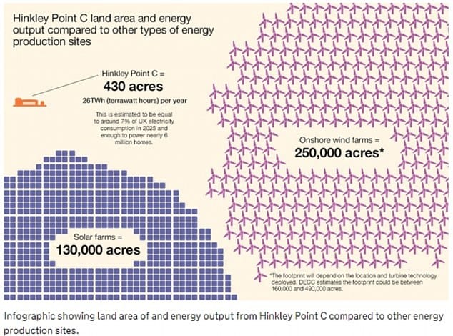
Germany’s green transition is a disaster. Twenty years ago, Germany had 23 nuclear power plants that generated 30% of the country’s electricity cleanly, cheaply, and reliably. These plants have all been shut by the government as part of a commitment to clean energy. What could be cleaner? Germany has switched to a mix of wind and solar, plus a significant shift to coal power. Wind and solar use a lot of land compared to nuclear, and they break down leaving fields of debris. There is now a lack of electricity to power homes and industries, and what power there is, is unreliable, due to the many dark windless days in Germany.
The lack of reliable electricity is crippling German industry now that Russian gas has been cut off. In this environment, why would the Germans order special trains and boats that burn, hydrogen that’s made from electricity and natural gas? The reason is that Germany sometimes has too much wind power and nothing to do with it. They plan to store this excess by making hydrogen that they can use to power their trains and boats. The cost is high, and the efficiency is poor, but the electricity is free.
A better answer would be battery storage, IMHO, or using the hydrogen to make liquid fuels (gasoline) from wood. Hydrogen is not a compact fuel like gasoline, but it’s cleaner. Compressing hydrogen to high pressure helps, and H2 storage is cheaper than batteries. Also, hydrogen fuel is transferred faster than electric fuels. Trains and ships are chosen for hydrogen because they can carry bulky items tanks. Also, many trains and boats are already powered by electricity. Hydrogen fuel cells can make the electricity on board (in theory), while avoiding the need for expensive overhead wires. The idea sort-of makes sense.
Germany’s first hydrogen train. cancelled after 1 year of poor operating.
The first hydrogen-powered train in Germany, The Hannover line, used fuel cells to generate electricity. It began service in October 2022, but the fuel cells proved unreliable, and service ended October 2023. For now, they are powered by polluting diesel (see here). They plan to switch to battery-powered trains over the next few years. A hydrogen-powered ferry is also planned, but it is not clear why the ferry should be more reliable than the train.
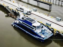
San Francisco’s hydrogen-powered ferry, $30 million, 15 knots top speed, 75 passengers, no cars. Long delayed.
In the US, the Biden administration has paid, so far, $30 million for a hydrogen ferry in San Francisco. It’s two years behind schedule and over cost, taking only 75 passengers and no cars at 15 knots, 17mph. In the US, and likely in Germany, most of the hydrogen will be made from natural gas. A better solution, I think would be to power the ferris and trains by natural gas and to store the excess electricity in land-based batteries or as land-based hydrogen for land-based fuel cells.
Germany is committed to electric trains, though, and hydrogen provides a route to power these trains with excess electricity. German customers take the train, in part, because they like them, and in part because German politicians have banned short-hop planes on competing routes, and subsidized electric trains. Yet another option to balance times of excess solar and wind power would be to subsidize electric cars, or at least allow theirs owners to trade electricity: to buy electricity when it’s cheap and resell it to the grid when demand and prices are high.
Heat exchange is a key part of most chemical process designs. Heat exchangers save money because they’re generally cheaper than heaters and the continuing cost of fuel or electricity to run the heaters. They also usually provide free, fast cooling for the product; often the product is made hot, and needs to be cooled. Hot products are usually undesirable. Free, fast cooling is good.
So how do you design a heat exchanger? A common design is to weld the right amount of tubes inside a shell, so it looks like the drawing below. The the hot fluid might be made to go through the tubes, and the cold in the shell, as shown, or the hot can flow through the shell. In either case, the flows are usually in the opposite direction so there is a hot end and a cold end as shown. In this essay, I’d like to discuss how I design our counter current heat exchangers beginning a common case (for us) where the two flows have the same thermal inertia, e.g. the same mass flow rates and the same heat capacities. That’s the situation with our hydrogen purifiers: impure hydrogen goes in cold, and is heated to 400°C for purification. Virtually all of this hot hydrogen exits the purifier in the “pure out” stream and needs to be cooled to room temperature or nearly.
Typical shell and tube heat exchanger design, Black Hills inc.
For our typical designs the hot flows in one direction, and an equal cold flow is opposite, I will show the temperature difference is constant all along the heat exchanger. As a first pass rule of thumb, I design so that this constant temperature difference is 30°C. That is ∆THX =~ 30°C at every point along the heat exchanger. More specifically, in our Mr Hydrogen® purifiers, the impure, feed hydrogen enters at 20°C typically, and is heated by the heat exchanger to 370°C. That is 30°C cooler than the final process temperature. The hydrogen must be heated this last 30°C with electricity. After purification, the hot, pure hydrogen, at 400°C, enters the heat exchanger leaving at 30°C above the input temperature, that is at 50°C. It’s hot, but not scalding. The last 30°C of cooling is done with air blown by a fan.
The power demand of the external heat source, the electric heater, is calculated as: Wheater = flow (mols/second)*heat capacity (J/°C – mol)* (∆Theater= ∆THX = 30°C).
The smaller the value of ∆THX, the less electric draw you need for steady state operation, but the more you have to pay for the heat exchanger. For small flows, I often use a higher value of ∆THX = 30°C, and for large flows smaller, but 30°C is a good place to start.
Now to size the heat exchanger. Because the flow rate of hot fluid (purified hydrogen) is virtually the same as for cold fluid (impure hydrogen), the heat capacity per mol of product coming out is the same as for mol of feed going in. Since enthalpy change equals heat capacity time temperature change, ∆H= Cp∆T, with effectiveCp the same for both fluids, and any rise in H in the cool fluid coming at the hot fluid, we can draw a temperature vs enthalpy diagram that will look like this:
The heat exchanger heats the feed from 20°C to 370°C. ∆T = 350°C. It also cools the product 350°C, that is from 400 to 50°C. In each case the enthalpy exchanged per mol of feed (or product is ∆H= Cp*∆T = 7*350 =2450 calories.
Since most heaters work in Watts, not calories, at some point it’s worthwhile to switch to Watts. 1 Cal = 4.174 J, 1 Cal/sec = 4.174 W. I tend to do calculations in mixed units (English and SI) because the heat capacity per mole of most things are simple numbers in English units. Cp (water) for example = 1 cal/g = 18 cal/mol. Cp (hydrogen) = 7 cal/mol. In SI units, the heat rate, WHX, is:
The flow rate in mols per second is the flow rate in slpm divided by 22.4 x 60. Since the driving force for transfer is 30°C, the area of the heat exchanger is WHX times the resistance divided by ∆THX:
A = WHX * R / 30°C.
Here, R is the average resistance to heat transfer, m2*∆T/Watt. It equals the sum of all the resistances, essentially the sum of the resistance of the steel of the heat exchanger plus that of the two gas phases:
R= δm/km + h1+ h2
Here, δm is the thickness of the metal, km is the thermal conductivity of the metal, and h1 and h2 are the gas-phase heat transfer parameters in the feed and product flow respectively. You can often estimate these as δ1/k1 and δ2/k2 respectively, with k1 and k2 as the thermal conductivity of the feed and product, both hydrogen in my case. As for, δ, the effective gas-layer thickness, I generally estimate this as 1/3 the thickness of the flow channel, for example:
h1 = δ1/k1 = 1/3 D1/k1.
Because δ is smaller the smaller the diameter of the tubes, h is smaller too. Also small tubes tend to be cheaper than big ones, and more compact. I thus prefer to use small diameter tubes and small diameter gaps. in my heat exchangers, the tubes are often 1/4″ or bigger, but the gap sizes are targeted to 1/8″ or less. If the gap size gets too low, you get excessive pressure drops and non-uniform flow, so you have to check that the pressure drop isn’t too large. I tend to stick to normal tube sizes, and tweak the design a few times within those parameters, considering customer needs. Only after the numbers look good to my aesthetics, do I make the product. Aesthetics plays a role here: you have to have a sense of what a well-designed exchanger should look like.
The above calculations are fine for the simple case where ∆THX is constant. But what happens if it is not. Let’s say the feed is impure, so some hot product has to be vented, leaving les hot fluid in the heat exchanger than feed. I show this in the plot at right for the case of 14% impurities. Sine there is no phase change, the lines are still straight, but they are no longer parallel. Because more thermal mass enters than leaves, the hot gas is cooled completely, that is to 50°C, 30°C above room temperature, but the cool gas is heated at only 7/8 the rate that the hot gas is cooled. The hot gas gives off 2450 cal as before, but this is now only enough to heat the cold fluid by 2450/8 = 306.5°. The cool gas thus leave the heat exchanger at 20°C+ 306.8° = 326.5°C.
The simple way to size the heat exchanger now is to use an average value for ∆THX. In the diagram, ∆THX is seen to vary between 30°C at the entrance and and 97.5°C at the exit. As a conservative average, I’ll assume that ∆THX = 40°C, though 50 to 60°C might be more accurate. This results in a small heat exchanger design that’s 3/4 the size of before, and is still overdesigned by 25%. There is no great down-side to this overdesign. With over-design, the hot fluid leaves at a lower ∆THX, that is, at a temperature below 50°C. The cold fluid will be heated to a bit more than to the 326.5°C predicted, perhaps to 330°C. We save more energy, and waste a bit on materials cost. There is a “correct approach”, of course, and it involves the use of calculous. A = ∫dA = ∫R/∆THX dWHX using an analytic function for ∆THX as a function of WHX. Calculating this way takes lots of time for little benefit. My time is worth more than a few ounces of metal.
The only times that I do the correct analysis is with flame boilers, with major mismatches between the hot and cold flows, or when the government requires calculations. Otherwise, I make an H Vs T diagram and account for the fact that ∆T varies with H is by averaging. I doubt most people do any more than that. It’s not like ∆THX = 30°C is etched in stone somewhere, either, it’s a rule of thumb, nothing more. It’s there to make your life easier, not to be worshiped.
The hydrogen economy is generally thought to come in some distant future, where your car (and perhaps your home) runs on hydrogen, and the hydrogen, presumably, is made by clean nuclear or renewable solar or wind power. This is understood to be better than the current state of things where your car runs on dirty gasoline, and your home runs on coal or gas, except when the sun is shining bright and the wind is blowing hard. Our homes and cars can not run on solar or wind alone, although solar cells have become quite cheap, because solar power is only available in the daytime, basically for 6 hours, from about 9AM to 3PM. Hydrogen has been proposed as a good way to store solar and wind energy that you can’t use, but it’s not easy to store hydrogen — or is it? I’d like to suggest that, to a decent extent, we already store green hydrogen and use it to run our trucks. We store this hydrogen in the form of Diesel fuel, so you don’t realize it’s hydrogen.
Much of the oil in the United States these days comes from tar sands and shale. It doesn’t flow well at room temperature, and is too heavy and gooey for normal use. We could distill this crude oil and use only the light parts, but that would involve throwing away a huge majority of the oil. Instead we steam reform it to gasoline, ethylene and other products. The reaction is something like this, presuming an input feed of naphtha, C10H8:
C10H8 + 2 H2O –> C7H8 + C2H4 + CO2.
The C2H4 component is ethylene. We use it to make plastics. The C7H8 is called toluene. It is a component of high octane gasoline (octane rating about 114). The inventor of the process, Eugene Jules Houdry claimed to have won WWII for the allies because his secret process (Houdryflow catalytic cracking) allowed high production of lots of gasoline of very high octane, giving US and British planes and trucks higher mpg than the Germans or Japanese had. It was a great money maker, but companies can make even more by adding hydrogen.
Schematic of the hydrocracking process, from the US energy information agency
Over the last 2-3 decades, refineries have been adding catalytic hydrogenation processes. These convert high octane aromatic products, like toluene to low -octane diesel and jet fuel. These products sell for more. Aromatic toluene is exposed to hydrogen at about 500°C and 300 psi (20 bar) to produce heptane, an excellent diesel fuel with about 7% more energy content than toluene per gallon.
C7H8 + 4H2 –> C7H16.
Diesel fuel sell for about 20% more than gasoline per gallon, in part because of the higher energy content, and because Diesel engines are more efficient than gas engines. What’s more, toluene expands as it’s converted to heptane. One gallon of toluene converts to 1.16 gallons of heptane. As a result hydrogenation adds about 40% to the sales price per molecule. Refineries have found that they can make significant money this way if they can buy cheap hydrogen. Over the last few years, several refineries in Norway and Texas (high sun and wind areas) have added hydrogenators along with electrolysis units to produce the cheap hydrogen when no one needs the unwanted electricity generated when supply exceeds demand. Here is an analysis of the thermodynamics of this type of hydrogen generation.
The main products of my company, REB Research, involve metallic membranes, often palladium-based, that provide 100% selective hydrogen filtering or long term hydrogen storage. One way to understand why these metallic membrane provide 100% selectivity has to do with the fact that metallic atoms are much bigger than hydrogen ions, with absolutely regular, small spaces between them that fit hydrogen and nothing else.
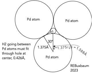
Palladium atoms are essentially spheres. In the metallic form, the atoms pack in an FCC structure (face-centered cubic) with a radius of, 1.375 Å. There is a cloud of free electrons that provide conductivity and heat transfer, but as far as the structure of the metal, there is only a tiny space of 0.426 Å between the atoms, see below. This hole is too small of any molecule, or any inert gas. In the gas phase hydrogen molecules are about 1.06 Å in diameter, and other molecules are bigger. Hydrogen atoms shrink when inside a metal, though, to 0.3 to 0.4 Å, just small enough to fit through the holes.
The reason that hydrogen shrinks has to do with its electron leaving to join palladium’s condition cloud. Hydrogen is usually put on the upper left of the periodic table because, in most cases, it behaves as a metal. Like a metal, it reacts with oxygen, and chlorine, forming stoichiometric compounds like H2O and HCl. It also behaves like a metal in that it alloys, non-stoichiometrically, with other metals. Not with all metals, but with many, Pd and the transition metals in particular. Metal atoms are a lot bigger than hydrogen so there is little metallic expansion on alloying. The hydrogen fits in the tiny spaces between atoms. I’ve previously written about hydrogen transport through transition metals (we provide membranes for this too).
No other atom or molecule fits in the tiny space between palladium atoms. Other atoms and molecules are bigger, 1.5Å or more in size. This is far too big to fit in a hole 0.426Å in diameter. The result is that palladium is basically 100% selective to hydrogen. Other metals are too, but palladium is particularly good in that it does not readily oxidize. We sometime sell transition metal membranes and sorbers, but typically coat the underlying metal with palladium.
We don’t typically sell products of pure palladium, by the way. Instead most of our products use, Pd-25%Ag or Pd-Cu. These alloys are slightly cheaper than pure Pd and more stable. Pd-25% silver is also slightly more permeable to hydrogen than pure Pd is — a win-win-win for the alloy.