My favorite fuel cells burn hydrogen-rich hydrocarbon fuels, like methane (natural gas) instead of pure hydrogen. Methane is far more energy dense, and costs far less than hydrogen per energy content. The US has plenty of methane and has pipelines that distribute it to every city and town. It’s a low CO2 fuel, and we can lower the CO2 impact further by mixing in hydrogen to get hythane. Elon Musk has called hydrogen- powered fuel cells “fool cells”, methane-powered fuel cells look a lot less foolish. They easily compete with his batteries and with gasoline. Besides, Musk has chosen methane as the fuel for his proposed starship to Mars.
Solid oxide fuel cells, SOFCs, can use methane directly without any pre-reformer. They operate at 800°C or so. At these temperatures, methane reacts with water (steam) within the fuel cell to form hydrogen by the reaction, CH4 + H2O –> 3H2 + CO. The hydrogen, and to a lesser extent the CO is oxidized in the fuel cell to create electricity,, but the methane is not 100% consumed, generally. Unused methane, CO, and some hydrogen exits a solid oxide fuel cell along with the products of combustion, CO2 and water.
Several researchers have looked for ways to recycle this waste fuel to capture the energy value. Six years ago, I patented a membrane method to extract the waste fuel and recycle it, see a description here. I now see this method as too complex, and have applied for a patent on a simpler version, shown below as Figure 1. As before the main work is done by a membrane but here I dispense with the water gas shift reactor, and many of the heat exchangers of the previous approach.
Simple way to improve fuel use in a high temperature fuel cell, using just a membrane.
The fuel cell system of Fig. 1 operates at somewhat elevated pressure, 2 atm or more. It is expected that the majority of the exhaust going to the membrane will be CO2 and water. Most of this will pass through the membrane and will exhaust to the air. The rest is mixed with fresh methane and recycles to the fuel cell. Despite the pressure of the fuel cell, very a little energy is needed for recirculation since the methane does not go through the membrane. The result is a light, simple, and energy efficient process. If you are interested, please contact me at REB Research. Or you can purchase the silicone membrane module here. Alternately, see here for flux information and other applications.
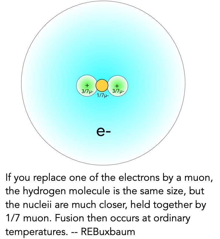
A hydrogen molecule consists of two protons held together by a covalent bond. One way to think of such bonds is to imagine that there is only one electron is directly involved as shown below. The bonding electron only spends 1/7 of its time between the protons, making the bond, the other 6/7 of the time the electron shields the two protons by 3/7 e– each, reducing the effective charge of each proton to 4/7e+.
We see that the two shielded protons will repel each other with the force of FR = Ke (16/49 e2 /r2) where e is the charge of an electron or proton, r is the distance between the protons (r = 0.74Å = 0.74×10⁻¹⁰m), and Ke is Coulomb’s electrical constant, Ke ≈ 8.988×10⁹ N⋅m2⋅C−2. The attractive force is calculated similarly, as each proton attracts the central electron by FA = – Ke (4/49) e2/ (r/2)2. The forces are seen to be in balance, the net force is zero.
It is because of quantum mechanics, that the bond is the length that it is. If the atoms were to move closer than r = 0.74Å, the central electron would be confined to less space and would get more energy, causing it to spend less time between the two protons. With less of an electron between them, FR would be greater than FA and the protons would repel. If the atoms moved further apart than 0.74Å, a greater fraction of the electron would move to the center, FA would increase, and the atoms would attract. This is a fairly pleasant way to understand why the hydrogen side of all hydrogen covalent bonds are the same length. It’s also a nice introduction to muon-catalyzed cold fusion.
Most fusion takes place only at high temperatures, at 100 million °C in a TOKAMAK Fusion reactor, or at about 15 million °C in the high pressure interior of the sun. Muon catalyzed fusion creates the equivalent of a much higher pressure, so that fusion occurs at room temperature. The trick to muon catalyzed fusion is to replace one of the electrons with a muon, an unstable, heavy electron particle discovered in 1936. The muon, designated µ-, behaves just like an electron but it has about 207 times the mass. As a result when it replaces an electron in hydrogen, it forms form a covalent bond that is about 1/207th the length of a normal bond. This is the equivalent of extreme pressure. At this closer distance, hydrogen nuclei fuse even at room temperature.
In normal hydrogen, the nuclei are just protons. When they fuse, one of them becomes a neutron. You get a deuteron (a proton-neutron pair), plus an anti electron and 1.44 MeV of energy after the anti-electron has annihilated (for more on antimatter see here). The muon is released most of the time, and can catalyze many more fusion reactions. See figure at right.
While 1.44MeV per reaction is a lot by ordinary standards — roughly one million times more energy than is released per atom when hydrogen is burnt — it’s very little compared to the energy it takes to make a muon. Making a muon takes a minimum of 1000 MeV, and more typically 4000 MeV using current technology. You need to get a lot more energy per muon if this process is to be useful.
You get quite a lot more energy when a muon catalyzes deuterium fusion or deuterium- fusion. With these reactions, you get 3.3 to 4 MeV worth of energy per fusion, and the muon will be ejected with enough force to support about eight D-D fusions before it decays or sticks to a helium atom. That’s better than before, but still not enough to justify the cost of making the muon.
The next reactions to consider are D-T fusion and Li-D fusion. Tritium is an even heavier isotope of hydrogen. It undergoes muon catalyzed fusion with deuterium via the reaction, D+T –> 4He +n +17.6 MeV. Because of the higher energy of the reaction, the muons are even less likely to stick to a helium atom, and you get about 100 fusions per muon. 100 x 17.6 MeV = 1.76 GeV, barely break-even for the high energy cost to make the muon, but there is no reason to stop there. You can use the high energy fusion neutrons to catalyze LiD fusion. For example, 2LiD +n –> 34He + T + D +n producing 19.9 MeV and a tritium atom.
With this additional 19.9 MeV per DT fusion, the system can start to produce usable energy for sale. It is also important that tritium is made in the process. You need tritium for the fusion reactions, and there are not many other supplies. The spare neutron is interesting too. It can be used to make additional tritium or for other purposes. It’s a direction I’d like to explore further. I worked on making tritium for my PhD, and in my opinion, this sort of hybrid operation is the most attractive route to clean nuclear fusion power.
There are two ASTM-approved methods for measuring the gas permeability of a material. The equipment is very similar, and REB Research makes equipment for either. In one of these methods (described in detail here) you measure the rate of pressure rise in a small volume.This method is ideal for high permeation rate materials. It’s fast, reliable, and as a bonus, allows you to infer diffusivity and solubility as well, based on the permeation and breakthrough time.
Exploded view of the permeation cell.
For slower permeation materials, I’ve found you are better off with the other method: using a flow of sampling gas (helium typically, though argon can be used as well) and a gas-sampling gas chromatograph. We sell the cells for this, though not the gas chromatograph. For my own work, I use helium as the carrier gas and sampling gas, along with a GC with a 1 cc sampling loop (a coil of stainless steel tube), and an automatic, gas-operated valve, called a sampling valve. I use a VECO ionization detector since it provides the greatest sensitivity differentiating hydrogen from helium.
When doing an experiment, the permeate gas is put into the upper chamber. That’s typically hydrogen for my experiments. The sampling gas (helium in my setup) is made to flow past the lower chamber at a fixed, flow rate, 20 sccm or less. The sampling gas then flows to the sampling loop of the GC, and from there up the hood. Every 20 minutes or so, the sampling valve switches, sending the sampling gas directly out the hood. When the valve switches, the carrier gas (helium) now passes through the sampling loop on its way to the column. This sends the 1 cc of sample directly to the GC column as a single “injection”. The GC column separates the various gases in the sample and determines the components and the concentration of each. From the helium flow rate, and the argon concentration in it, I determine the permeation rate and, from that, the permeability of the material.
As an example, let’s assume that the sample gas flow is 20 sccm, as in the diagram above, and that the GC determines the H2 concentration to be 1 ppm. The permeation rate is thus 20 x 10-6 std cc/minute, or 3.33 x 10⁻⁷ std cc/s. The permeability is now calculated from the permeation area (12.56 cm2 for the cells I make), from the material thickness, and from the upstream pressure. Typically, one measures the thickness in cm, and the pressure in cm of Hg so that 1 atm is 76cm Hg. The result is that permeability is determined in a unit called barrer. Continuing the example above, if the upstream hydrogen is 15 psig, that’s 2 atmospheres absolute or or 152 cm Hg. Lets say that the material is a polymer of thickness is 0.3 cm; we thus conclude that the permeability is 0.524 x 10⁻¹⁰ scc/cm/s/cm2/cmHg = 0.524 barrer.
This method is capable of measuring permeabilities lower than the previous method, easily lower than 1 barrer, because the results are not fogged by small air leaks or degassing from the membrane material. Leaks of oxygen, and nitrogen show up on the GC output as peaks that are distinct from the permeate peak, hydrogen or whatever you’re studying as a permeate gas. Another plus of this method is that you can measure the permeability of multiple gas species simultaneously, a useful feature when evaluating gas separation polymers. If this type of approach seems attractive, you can build a cell like this yourself, or buy one from us. Send us an email to reb@rebresearch.com/blog/, or give us a call at 248-545-0155.
One of the founding ideas of a limited government, as I think our founders intended, is that the power of the state to protect carries with it several dangers. The first of these is cost, all good services and all good protections come at a cost. Generally that is achieved by taxation or by inflation, or by imposing regulations that do more harm than good. Once a tax for a service is accepted the service is really removed, and there is a tendency to over tax or over inflate to maintain it and to mis-distribute the service as well. The people do not become wealthier, or better served, but the people distributing the services win out. There are those who would say we are living through this today.
Another problem with a big, protective government is that the protectors can turn on the people they are supposed to protect. This can be small issues, like firing people who refuse to vaccinate, or large matters like imprisoning enemies. The history of the world is littered with examples of governments taken over by their own police or army. Generally the excuse is that the police is protecting the people from some bigger danger: rioters, disease, subversives. But once the police take over, they are hard to remove. They tend to see anyone who wants to limit their power as another subversive, and they tend to treat treat such people ruthlessly.
In the French Revolution, the group who ran the guillotine was the “committee for public safety”. First they killed to protect the folk from dangerous monarchists, then the clergy, and capitalists, and eventually anyone they considered a threat: That is anyone who considered them a threat. A similar outcome occurred in Russia, the removal of the Tzar lead to a rein of terror by Stalin. Harry Truman wrote saying that the CIA was another Stalinist police force, and wrote that congress was afraid of them. (see his Op-ed here). It seems that FBI director James Comey used made-up evidence of Russian collaboration to try to remove Trump (see NY Post story here).
A final problem with a powerful group of protectors is that it can be bought by outside agents. Rudolf Hess was Truman’s agent for dealing with the UN to promote world peace. It also turns out that he was also a Soviet agent. In Britain in the 50s to 70s, the assistant head of spying, the second in command of MI6, was Kim Philby a Soviet agent. The Soviets helped Philby’s rise by destroying the reputation of anyone who might do the job well. To this day, we regularly find Chinese and Russian agents in our FBI, NSA, and CIA. There is no better place to gather information and spread lies than with the organization that is supposed to protect us.
The title of my essay comes from a satrical poem/ essay written by Juvinal, in first century Rome (read it here). The more famous line is Quis custodiet ipsos custodes? Juvenal points out that not only is group of watchmen/protectors a danger in itself so that, if you hire a watchman to keep your wife chaste, she is likely to stray with the watchman, but he also points out that the watchmen are expensive, and that they are easily bought. Juvenal also points out that cruelty and vanities are common outcomes of a large retinue; if the wife or one of her high eunuchs feels disregarded, everyone lower will be beaten mercilessly. It’s a problem that is best solved, in the home and in politics in general by having a small staff — just what’s really needed. This, I think, was the intent of the founders of our country who limited the number of services provided.
Robert E. Buxbaum, November 27, 2021. As a more-fun way to present watchmen getting excessive, here is a parity song, “Party in the CIA,” by Weird Al. …Better put your hands up and get in the van, Or else you’ll get blown away, Stagin’ a coup like yeah… Party in the CIA.
Platinum catalysts can be very effective at removing hydrogen from air. Platinum promotes the irreversible reaction of hydrogen with oxygen to make water: H2 + 1/2 O2 –> H2O, a reaction that can take off, at great rates, even at temperatures well below freezing. In the 1800s, when platinum was cheap, platinum powder was used to light town-gas, gas street lamps. In those days, street lamps were not fueled by methane, ‘natural gas’, but by ‘town gas’, a mix of hydrogen and carbon monoxide and many impurities like H2S. It was made by reacting coal and steam in a gas plant, and it is a testament to the catalytic power of Pt that it could light this town gas. These impurities are catalytic poisons. When exposed to any catalyst, including platinum, the catalyst looses it’s power to. This is especially true at low temperatures where product water condenses, and this too poisons the catalytic surface.
Nowadays, platinum is expensive and platinum catalysts are no longer made of Pt powder, but rather by coating a thin layer of Pt metal on a high surface area substrate like alumina, ceria, or activated carbon. At higher temperatures, this distribution of Pt improves the reaction rate per gram Pt. Unfortunately, at low temperatures, the substrate seems to be part of the poisoning problem. I think I’ve found a partial way around it though.
My company, REB Research, sells Pt catalysts for hydrogen removal use down to about 0°C, 32°F. For those needing lower temperature hydrogen removal, we offer a palladium-hydrocarbon getter that continues to work down to -30°C and works both in air and in the absence of air. It’s pretty good, but poisons more readily than Pt does when exposed to H2S. For years, I had wanted to develop a version of the platinum catalyst that works well down to -30°C or so, and ideally that worked both in air and without air. I got to do some of this development work during the COVID downtime year.
My current approach is to add a small amount of teflon and other hydrophobic materials. My theory is that normal Pt catalysts form water so readily that the water coats the catalytic surface and substrate pores, choking the catalyst from contact with oxygen or hydrogen. My thought of why our Pd-organic works better than Pt is that it’s part because Pd is a slower water former, and in part because the organic compounds prevent water condensation. If so, teflon + Pt should be more active than uncoated Pt catalyst. And it is so.
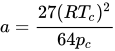
where is molar volume. The substance-specific constants and can be understood as an attraction force between molecules and a molecular volume respectively. Alternately, they can be calculated from the critical temperature and pressure as
Now, I’m going to assume that the effect of a hydrophobic surface near the Pt is to reduce the effective value of a. This is to say that water molecules still attract as before, but there are fewer water molecules around. I’ll assume that b remains the same. Thus the ratio of Tc and Pc remains the same but the values drop by a factor of related to the decrease in water density. If we imagine the use of enough teflon to decrease he number of water molecules by 60%, that would be enough to reduce the critical temperature by 60%. That is, from 647 K (374 °C) to 359 K, or -14°C. This might be enough to allow Pt catalysts to be used for H2 removal from the gas within a nuclear wast casket. I’m into nuclear, both because of its clean power density and its space density. As for nuclear waste, you need these caskets.
I’ve begun to test of my theory by making hydrogen removal catalyst that use both platinum and palladium along with unsaturated hydrocarbons. I find it works far better than the palladium-hydrocarbon getter, at least at room temperature. I find it works well even when the catalyst is completely soaked in water, but the real experiments are yet to come — how does this work in the cold. Originally I planned to use a freezer for these tests, but I now have a better method: wait for winter and use God’s giant freezer.
It’s been a while since I did an assessment of hydrogen and batteries for automobile propulsion, and while some basics have not changed, the price and durability of batteries has improved, the price of gasoline has doubled, and the first commercial fuel cell cars have appeared in the USA. The net result (see details below) is that I find the cost of ownership for a gasoline and a battery car is now about the same, depending on usage and location, and that hydrogen, while still more pricey, is close to being a practical option.
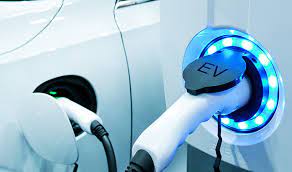
EV Chargers. They look so much cooler than gasoline hoses, and the price per mile is about the same.
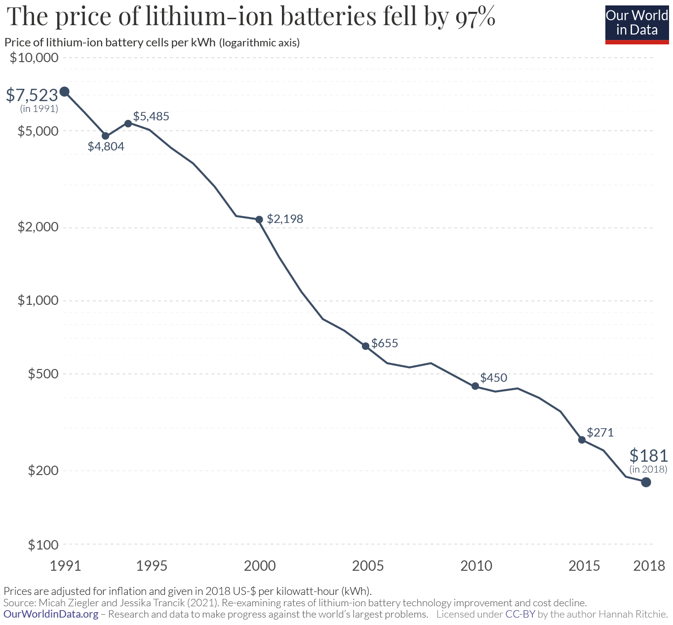
Lithium battery costs are now about $150/kwh. That’s $10,000 for a 70 kWh battery. That’s about 1/5 the price of a Tesla Model 3. The reliability that Tesla claims is 200,000 miles or more, but that’s with slow charging. For mostly fast charging, Car and Driver’s expectation is 120,000 miles. That’s just about the average life-span of a car these days.
The cost of the battery and possible replacement adds to the cost of the vehicle, but electricity is far cheaper than gasoline, per mile. The price of gasoline has doubled to, currently, $3.50 per gallon. A typical car will get about 24 mpg, and that means a current operation cost of 14.6¢/mile. That’s about $1,460/year for someone who drives 10,000 miles per year. I’ll add about $150 for oil and filter changes, and figure that operating a gas-powered car engine costs about $1,610 per year.
If you charge at home, your electricity costs, on average, 14¢/kWh. This is a bargain compared to gasoline since electricity is made from coal and nuclear, mostly, and is subsidized while gasoline is taxed. At level 2 charging stations, where most people charge, electricity costs about 50¢/kWh. This is three times the cost of home electricity, but it still translates to only about $32 for a fill-up that take 3 hours. According to “Inside EVs”, in moderate temperatures, a Tesla Model 3 uses 14.59 kWh/100 km with range-efficient driving. This translates to 11.7¢ per mile, or $1170/year, assuming 10,000 miles of moderate temperature driving. If you live in moderate climates: Californian, Texas or Florida, an electric car is cheaper to operate than a gasoline car. In cold weather gasoline power still makes sense since a battery-electric car uses battery power for heat, while a gasoline powered car uses waste heat from the engine.
Battery cars are still somewhat of more expensive than the equivalent gasoline car, but not that much. In a sense you can add $400/year for the extra cost of the Tesla above, but that just raises the effective operating cost to about $1,570/year, about the same as for the gasoline car. On the other hand, many folks drive less than 50 miles per day and can charge at home each night. This saves most of the electric cost. In sum, I find that EVs have hit a tipping point, and Tesla lead the way.
Now to consider hydrogen. When most people think hydrogen, they think H2 fuel, and a PEM fuel cell car. The problem here is that hydrogen is expensive, and PEM FCs aren’t particularly efficient. Hydrogen costs about $10/kg at a typical fueling station and, with PEM, that 1 kg of hydrogen takes you only about 25 miles. The net result is that the combination hydrogen + PEM results in a driving cost of about 40¢/mile, or about three times the price of gasoline. But Toyota has proposed two better options. The fist is a PEM hybrid, the hydrogen Prius. It’s for the commuter who drives less than about 40 miles per day. It has a 10kWh battery, far cheaper than the Tesla above, but enough for the daily commute. He or she would use charge at home at night, and use hydrogen fuel only when going on longer trips. If there are few long trips, you come out way ahead.
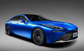
Toyota 2021 Mirai, hydrogen powered vehicle
Toyota also claims to have a hydrogen powered Corolla or debut in 2023. This car will have a standard engine, and I would expect (hope) will drive also — preferably — on hythane, a mix of hydrogen and methane. Hythane is much cheaper per volume, and more energy dense, see my analysis. While Toyota has not said that their Corolla would run on hythane, it is supposed to have an internal combustion engine, and that suggests that hythane will work in it.
A more advanced option for Toyota or any other car/truck manufacturer would be to design to use solid oxide fuel cells, SOFCs, either with hydrogen or hythane. SOFCs are significantly more efficient than PEM, and they are capable of burning hythane, and to some extent natural gas too. Hythane is not particularly available, but it could be. Any station that currently sells natural gas could sell hythane. As for delivery to the station, natural gas lines already exist underground, and the station would just blend in hydrogen, produced at the station by electrolysis, or delivered. Hythane can also be made locally from sewer gas methane, and wind-power hydrogen. Yet another SOFC option is to start with natural gas and convert some of the natural gas to hydrogen on-board using left-over heat from the SOFC. I’ve a patent for this process.
Speaking of supply network, I should mention the brown outs we’ve been having in Detroit. Electric cars are part of the stress to the electric grid, but I believe that, with intelligent charging (and discharging) the concern is more than manageable. The driver who goes 10,000 miles per year only adds about 2,350 kWh/year of extra electric demand. This is a small fraction of the demand of a typical home, 12,154 kWh/year.It’s manageable. Then again, hythane adds no demand to the electric grid and the charge time is quicker — virtually instantaneous.
I month ago, I wrote to endorse hythane, a mix of natural gas (methane) and 20-40% hydrogen. This mix is ideal for mobile use in solid oxide fuel cell vehicles, and not bad with normal IC engines. I’d now like to write about the advantages of an on-broad hydrogen generator to allow adjustable composition fuel mixes.
A problem you may have noticed with normal car engines is that a high hp engine will get lower miles per gallon, especially when you’re driving slow. That seems very strange; why should a bigger engine use more gas than a dinky engine, and why should you get lower mpg when you drive slow. The drag force on a vehicle is proportional to speed squared. You’d expect better milage at low speeds– something that textbooks claim you will see, counter to experience.
Behind these two problems are issues of fuel combustion range and pollution. You can solve both issues with hydrogen. With normal gasoline or Diesel engines, you get more or less the same amount of air per engine rotation at all rpm speeds, but the amount of air is much higher for big engines. There is a relatively small range of fuel-air mixes that will burn, and an even smaller range that will burn at low pollution. You have to add at least the minimal fuel per rotation to allow the engine to fire. For most driving that’s the amount the carburetor delivers. Because of gearing, your rpm is about the same at all speeds, you use almost the same rate of fuel at all speeds, with more fuel used in big engines. A gas engine can run lean, but normally speaking it doesn’t run at all any leaner than about 1.6 times the stoichiometric air-to-fuel mix. This is called a lambda of 1.6. Adding hydrogen extends the possible lambda range, as shown below for a natural gas – fired engine.
Engine efficiency when fueled with natural gas plus hydrogen as a function of hydrogen amount and lambda, the ratio of air to stoichiometric air.
The more hydrogen in the mix the wider the range, and the less pollution generally. Pure hydrogen burns at ten times stoichiometric air, a lambda of ten. There is no measurable pollution there, because there is no carbon to form CO, and temperature is so low that you don’t form NOx. But the energy output per rotation is low (there is not much energy in a volume of hydrogen) and hydrogen is more expensive than gasoline or natural gas on an energy basis. Using just a little hydrogen to run an engine at low load may make sense, but the ideal mix of hydrogen and ng fuel will change depending on engine load. At high load, you probably want to use no hydrogen in the mix.
As it happens virtually all of most people’s driving is at low load. The only time when you use the full horse-power is when you accelerate on a highway. An ideal operation for a methane-fueled car would add hydrogen to the carburetor intake at about 1/10 stoichiometric when the car idles, turning down the hydrogen mix as the load increases. REB Research makes hydrogen generators based on methanol reforming, but we’ve yet to fit one to a car. Other people have shown that adding hydrogen does improve mpg.
Carburetor Image from a course “Farm Power”. See link here. Adding hydrogen means you could use less gas.
Adding hydrogen plus excess air means there is less pollution. There is virtually no CO at idle because there is virtually no carbon, and even at load because combustion is more efficient. The extra air means that combustion is cooler, and thus you get no NOx or unburned HCs, even without a catalytic converter. Hydrogen is found to improve combustion speed and extent. A month ago, I’d applied for a grant to develop a hydrogen generator particularly suited to methane engines. Sorry to say, the DoT rejected my proposal.
Some years ago I wrote a largely negative review of Brown’s gas, but the COVID crisis in India makes me want to reconsider. Browns gas can provide a simple source of oxygen for those who are in need. First, an explanation, Browns gas is a two-to-one mix of hydrogen and oxygen; it’s what you get when you do electrolysis of water without any internal separator. Any source of DC electricity will do, e.g. the alternator of a car or a trickle charger of the sort folks buy for their car batteries, and almost any electrode will do too (I’d suggest stainless steel). You can generate pressure just by restricting flow from the electrolysis vessel, and it can be a reasonable source of small-scale oxygen or hydrogen. The reaction is:
H2O –> H2 + 1/2 O2.
The problem with Brown’s gas is that it is explosive, more explosive than hydrogen itself, so you have to handle it with care; avoid sparks until you separate the H2 from the O2. Even the unseparated mix has found some uses, e.g. as a welding gas, or for putting in cars to avoid misfires, increase milage, and decrease pollution. I think that methanol reforming is a better source of automotive hydrogen: hydrogen is a lot safer than this hydrogen-oxygen mix.
Browns gas to oxygen for those who need it.
The mix is a lot less dangerous if you separate the oxygen from the hydrogen with a membrane, as I show in the figure. at right. If you do this it’s a reasonable wy to make oxygen for patients who need oxygen. The electrolysis cell can be a sealed bottle with water and the electrodes; add a flow restriction as shown to create the hydrogen pressure that drives the separation. The power can be an automotive trickle charger. You can get this sort of membranes from REB Research, here and many other suppliers. REB provide consulting services if you like.
In a pinch, you don’t even need the membrane, by the way. You can rely on your lungs to make the separation. A warning, though, the mix is dangerous. Avoid all sparks. Also, don’t put salt into the water. You can can put in some baking soda or lye to speed the electrolysis, but If you put salt in, you’ll find you don’t make oxygen, but will instead make chlorine. And chlorine is deadly. If you’re not sure, smell the gas. If it smells acrid, don’t use it. This is the chlorine-forming reaction.
2NaCl + 2 H2O –> H2 + Cl2 + 2NaOH
Ideally you should vent the hydrogen stream out the window, but for short term, emergency use, the hydrogen can be vented into your home. Don’t do this if anyone smokes (not that anyone should smoke about someone on oxygen). This is a semi-patentable design, but I’m giving it away; not everything that can be patented should be.
Fuel cells are highly efficient and hardly polluting. They have a long history of use in space, and as a power source for submarines. They are beginning to appear powering city buses and intercity trains, at least in Europe, but not so much in the US or Canada. The business case for fuel cells is that they provide clean electric power to the train or bus, without the need for overhead wires. Avoiding wires helps make up for the high cost of hydrogen as a fuel. The reluctance to switch to fuel cells is the US is due to the longer distances that must be covered. The very low volumetric energy density of hydrogen means you need many filling stations with hydrogen fuel cells, and many fill ups per trip.
Energy density CNG, hydrogen, hythane.
On a mass-basis, hydrogen is energy dense, with 1 kg providing the same energy as 2-3 kg of gasoline. The problem with hydrogen (aside from the cost) is that its mass density is very low, less than 50g/liter, even at high pressure. This is terribly un-dense on a volume basis. It would take 20 liters of high pressure hydrogen (about 5 gallons) to take a car or bus as far as with one gallon of gasoline. Even with a huge tank of high pressure hydrogen, 150 gallons or so, a cross country trip would require some 12 fill ups, one every 250 miles, and this is an annoyance, besides being an infrastructure problem.
Then there is cost. In California, hydrogen costs far more than gasoline, between $12 and $15 per kg. That’s ten times as expensive as gasoline on a weight basis and 4 times as expensive on an energy basis. What’s needed is a cheaper, more energy-dense version of hydrogen, ideally one that can be used in both fuel cells and IC engines, and the version I’d like to suggest is hythane, a mix of methane (natural gas) and 20-30% hydrogen.
Hythane dispenser
Hythane has about 3 times the volumetric energy density of hydrogen, and about 1/3 the price. It makes less CO and CO2 pollution because there is far less carbon. On an energy basis, hythane costs just slightly more than gasoline, and requires less infrastructure. Natural gas is cheap and available, delivered by pipeline, without the need for hydrogen delivery trucks. Because hythane has about three times the volumetric energy density of hydrogen, the tank described above, that would give a 250 mile ride with hydrogen, would give 750 miles with hythane. This means a lot fewer fueling stations are needed, and a lot fewer forced stops. As a bonus, hythane can be used in (some) IC engines as well as in fuel cells.
Hydrogen for hythane-automotive use can be made on site, by electrolysis of water. Because there is relatively little hydrogen in the mix, only 25% by volume, or 8% on an energy basis, there is relatively little burden on the electric grid, and fueling will be a lot faster than with battery chargers. Hythane is already in use in buses in China and Canada. These are normal combustion buses but hythane works even better — more efficiently — with fuel cells (solid oxide fuel cells) and thus hythane provides a path to efficiency and greater fuel cell use.
Hythane bus, Montreal.
Natural gas does not work as well in fuel cells; it requires a pre-reformer to make some H2, and even then tends to coke. To be used in most fuel cells, the methane has to be converted, at lest partially into hydrogen and this takes heat energy and water.
CH4 + H2O + energy –> 3H2 + CO
Reforming is a lot easier with hythane; it can be done within the fuel cell. Within a SOFC, the hydrogen combustion, H2 + 1/2 O2 –> H2O, provides heat and water that helps feed the reforming reaction and helps prevent coking. Long term, fuel cells will likely dominate the energy future, but for now it’s nice to have a fuel that will work well in normal IC engines too.
The hope diamond resides in the Smithsonian. It really is a deep blue. It has about 5 ppm boron.
If you’ve ever seen the Hope Dimond, or a picture of it, you’ll notice a most remarkable thing: it is deep blue. While most diamonds are clear, or perhaps grey, a very few are colored. Color in diamonds is generally caused by impurities, in the case of blue diamonds, boron. The Hope diamond has about 5 ppm boron, making it a p-semiconductor. Most blue diamonds, even those just as blue, have less boron. As it turns out one of the major uses of my hydrogen purifiers hydrogen these days is in the manufacture of gem -quality, and semiconductor diamonds, some blue and some other colors. So I thought I’d write about diamonds, colored and not, natural and CVD. It’s interesting and a sort of plug for my company, REB Research.
To start off, natural diamond are formed, over centuries by the effect of high temperature and pressure on a mix of carbon and a natural catalyst mineral, Kimberlite. Diamonds formed this way are generally cubic, relatively clear, and inert, hard, highly heat conductive, and completely non-conducting of electricity. Some man made diamonds are made this way too, using high pressure presses, but gem-quality and semiconductor diamonds are generally made by chemical vapor deposition, CVD. Colored diamonds are made this way too. They have all the properties of clear diamonds, but they have controlled additions and imperfections. Add enough boron, 1000 ppm for example, and the diamond and the resulting blue diamond can conduct electricity fairly readily.
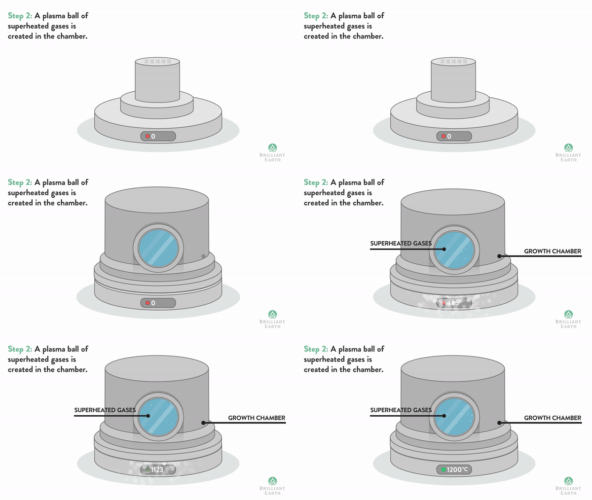
Seeds of natural diamond are placed in a diamond growth chamber and heated to about 1000°C in the presence of ionized, pure methane and hydrogen.
While natural diamond are sometimes used for technical applications, e.g. grind wheels, most technical-use diamonds are man-made by CVD, but the results tend to come out yellow. This was especially true in the early days of manufacture. CVD tends to make large, flat diamonds. This is very useful for heat sinks, and for diamond knives and manufacturers of these were among my first customers. To get a clear color, or to get high-quality colored diamonds, you need a mix of high purity methane and high purity hydrogen, and you need to avoid impurities of silica and the like from the diamond chamber. CVD is also used to make blue-conductive diamonds that can be used as semiconductors or electrodes. The process is show in the gif above from “brilliantearth”.
Multicolored diamonds made by CVD with many different dopants and treatments.
To make a CVD diamond, you place 15 to 30 seed- diamonds into a vacuum growth chamber with a flow of methane and hydrogen in ratio of 1:100 about. You heat the gas to about 1000°C (900-1200°C) , while ionizing the gas using microwaves or a hot wire. The diamonds grow epitaxially over the course of several days or weeks. Ionized hydrogen keeps the surface active, while preventing it from becoming carbonized — turning to graphite. If there isn’t enough hydrogen, you get grey, weak diamonds. If the gas isn’t pure, you get inclusions that make them appear yellow or brown. Nitrogen-impure diamonds are n-semiconductors, with a band gap greater than with boron-blue diamonds, 0.5-1 volts more. Because of this difference, nitrogen-impure diamonds absorb blue or green light, making them appear yellow, while blue diamonds absorb red light, making them blue. (This is different from the reason the sky is blue, explained here.) The difference in energy, also makes yellow diamonds poor electrical conductors. Natural, nitrogen-impure diamonds fluoresce blue or green, as one might expect, but yellow diamonds made by CVD fluoresce at longer wavelengths, reddish (I don’t know why).
The blue moon diamond, it is about as blue as the hope diamond though it has only 0.36 ppm of boron.
To make a higher-quality, yellow, n-type CVD diamonds, use very pure hydrogen. Bright yellow and green color is added by use of ppm-quantities of sulfur or phosphorus. Radiation damage also can be used to add color. Some CVD diamond makers use heat treatment to modify the color and reduce the amount of red fluorescence. CVD pink and purple diamonds are made by hydrogen doping, perhaps followed by heat treatment. The details are proprietary secrets.
Orange-red phosphorescence in the blue moon diamond.
Two major differences help experts distinguish between natural and man-made diamonds. One of these is the fluorescence, Most natural diamonds don’t fluoresce at all, and the ones that do (about 25%) fluoresce blue or green. Almost all CVD diamonds fluoresce orange-red because of nitrogen impurities that absorb blue lights. If you use very pure, nitrogen-free hydrogen, you get clear diamonds avoid much of the fluorescence and yellow. That’s why diamond folks come to us for hydrogen purifiers (and generators). There is a problem with blue diamonds, in that both natural and CVD-absorb and emit red light (that’s why they appear blue). Fortunately for diamond dealers, there is a slight difference in the red emission spectrum between natural and CVD blue diamonds. The natural ones show a mix of red and blue-green. Synthetic diamonds glow only red, typically at 660 nm.
Blue diamonds would be expected to fluoresce red, but instead they show a delayed red fluorescence called phosphorescence. That is to say, when exposed to light, they glow red and continue to glow for 10-30 seconds after the light is turned off. The decay time varies quite a lot, presumably due to differences in the n and p sites.
Natural diamond photographed between polarizers show patterns that radiate from impurities.
Natural and CVD also look different when placed between crossed polarizers. Natural diamonds show multiple direction stress bands, as at left, often radiating from inclusions. CVD diamonds show fine-grained patterns or none at all (they are not made under stress), and man-made, compression diamonds show an X-pattern that matches the press-design, or no pattern at all. If you are interested in hydrogen purifiers, or pure hydrogen generators, for this or any other purposes, please consider REB Research. If you are interested in buying a CVD diamond, there are many for sale, even from deBeers.
Robert Buxbaum, October 19, 2020. The Hope diamond was worn by three French kings, by at least one British king, and by Miss Piggy. A CVD version can be worn by you.




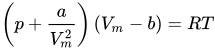
 is
is  and
and  can be understood as an attraction force between molecules and a molecular volume respectively. Alternately, they can be calculated from the