Category Archives: REB Research products

Isotopic effects in hydrogen diffusion in metals

For most people, there is a fundamental difference between solids and fluids. Solids have long-term permanence with no apparent diffusion; liquids diffuse and lack permanence. Put a penny on top of a dime, and 20 years later the two coins are as distinct as ever. Put a layer of colored water on top of plain water, and within a few minutes you’ll see that the coloring diffuse into the plain water, or (if you think the other way) you’ll see the plain water diffuse into the colored.

Now consider the transport of hydrogen in metals, the technology behind REB Research’s metallic  membranes and getters. The metals are clearly solid, keeping their shapes and properties for centuries. Still, hydrogen flows into and through the metals at a rate of a light breeze, about 40 cm/minute. Another way of saying this is we transfer 30 to 50 cc/min of hydrogen through each cm2 of membrane at 200 psi and 400°C; divide the volume by the area, and you’ll see that the hydrogen really moves through the metal at a nice clip. It’s like a normal filter, but it’s 100% selective to hydrogen. No other gas goes through.

To explain why hydrogen passes through the solid metal membrane this way, we have to start talking about quantum behavior. It was the quantum behavior of hydrogen that first interested me in hydrogen, some 42 years ago. I used it to explain why water was wet. Below, you will find something a bit more mathematical, a quantum explanation of hydrogen motion in metals. At REB we recently put these ideas towards building a membrane system for concentration of heavy hydrogen isotopes. If you like what follows, you might want to look up my thesis. This is from my 3rd appendix.

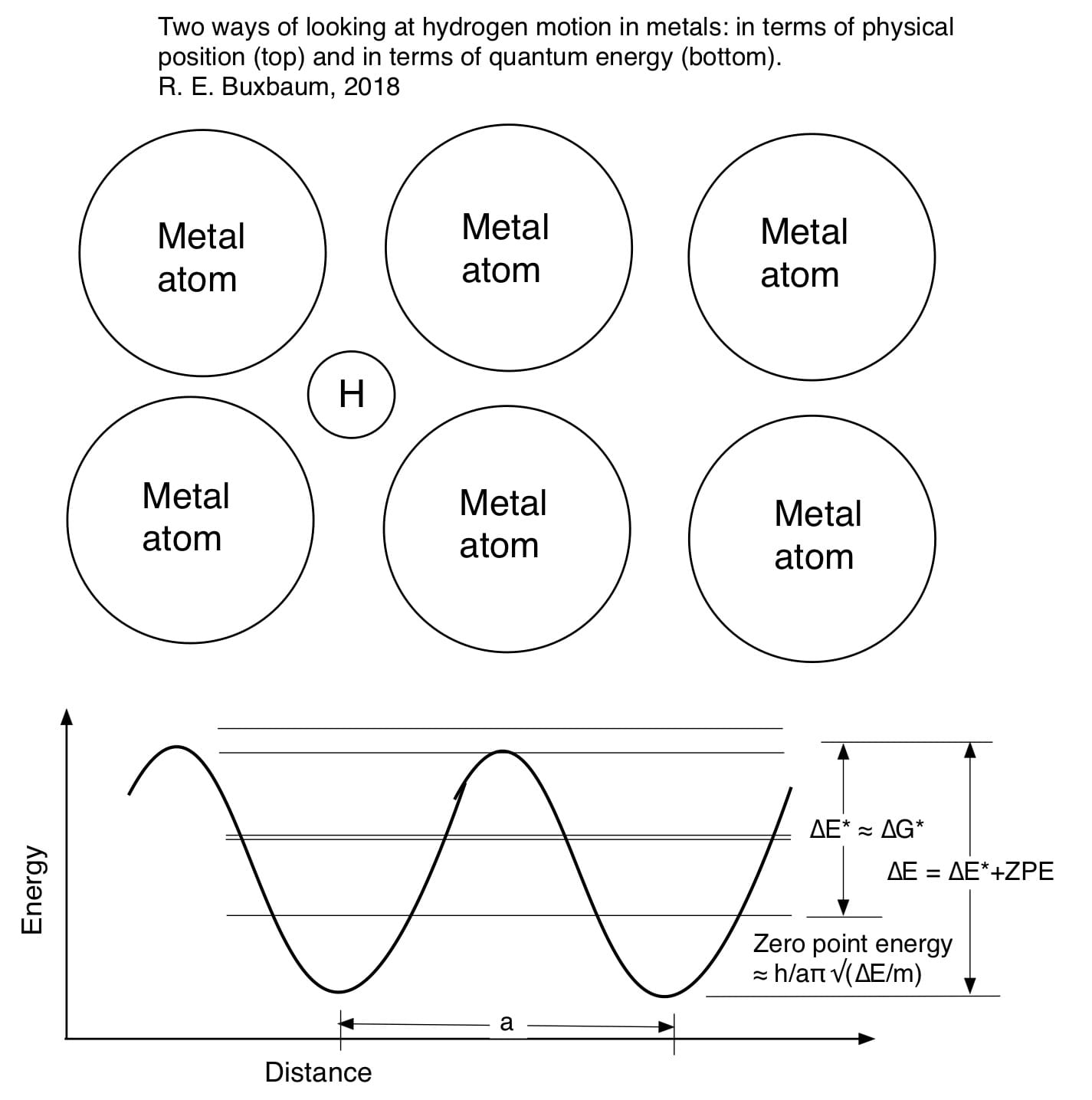
Although no-one quite understands why nature should work this way, it seems that nature works by quantum mechanics (and entropy). The basic idea of quantum mechanics you will know that confined atoms can only occupy specific, quantized energy levels as shown below. The energy difference between the lowest energy state and the next level is typically high. Thus, most of the hydrogen atoms in an atom will occupy only the lower state, the so-called zero-point-energy state.

A hydrogen atom, shown occupying an interstitial position between metal atoms (above), is also occupying quantum states (below). The lowest state, ZPE is above the bottom of the well. Higher energy states are degenerate: they appear in pairs. The rate of diffusive motion is related to ∆E* and this degeneracy.

A hydrogen atom, shown occupying an interstitial position between metal atoms (above), is also occupying quantum states (below). The lowest state, ZPE is above the bottom of the well. Higher energy states are degenerate: they appear in pairs. The rate of diffusive motion is related to ∆E* and this degeneracy.

The fraction occupying a higher energy state is calculated as c*/c = exp (-∆E*/RT). where ∆E* is the molar energy difference between the higher energy state and the ground state, R is the gas constant and T is temperature. When thinking about diffusion it is worthwhile to note that this energy is likely temperature dependent. Thus ∆E* = ∆G* = ∆H* – T∆S* where asterisk indicates the key energy level where diffusion takes place — the activated state. If ∆E* is mostly elastic strain energy, we can assume that ∆S* is related to the temperature dependence of the elastic strain.

Thus,

∆S* = -∆E*/Y dY/dT

where Y is the Young’s modulus of elasticity of the metal. For hydrogen diffusion in metals, I find that ∆S* is typically small, while it is often typically significant for the diffusion of other atoms: carbon, nitrogen, oxygen, sulfur…

The rate of diffusion is now calculated assuming a three-dimensional drunkards walk where the step lengths are constant = a. Rayleigh showed that, for a simple cubic lattice, this becomes:

D = a2/6τ

a is the distance between interstitial sites and t is the average time for crossing. For hydrogen in a BCC metal like niobium or iron, D=

a2/9τ; for a FCC metal, like palladium or copper, it’s

a2/3τ. A nice way to think about τ, is to note that it is only at high-energy can a hydrogen atom cross from one interstitial site to another, and as we noted most hydrogen atoms will be at lower energies. Thus,

τ = ω c*/c = ω exp (-∆E*/RT)

where ω is the approach frequency, or the amount of time it takes to go from the left interstitial position to the right one. When I was doing my PhD (and still likely today) the standard approach of physics writers was to use a classical formulation for this time-scale based on the average speed of the interstitial. Thus, ω = 1/2a√(kT/m), and

τ = 1/2a√(kT/m) exp (-∆E*/RT).

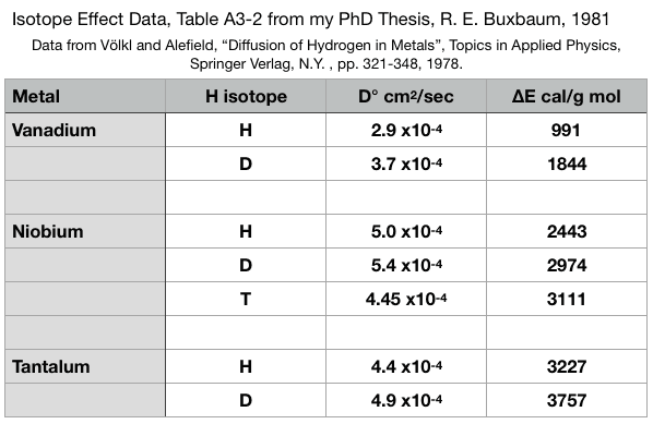
In the above, m is the mass of the hydrogen atom, 1.66 x 10⁻²⁴ g for protium, and twice that for deuterium, etc., a is the distance between interstitial sites, measured in cm, T is temperature, Kelvin, and k is the Boltzmann constant, 1.38 x 10⁻¹⁶ erg/°K. This formulation correctly predicts that heavier isotopes will diffuse slower than light isotopes, but it predicts incorrectly that, at all temperatures, the diffusivity of deuterium is 1/√2 that for protium, and that the diffusivity of tritium is 1/√3 that of protium. It also suggests that the activation energy of diffusion will not depend on isotope mass. I noticed that neither of these predictions is borne out by experiment, and came to wonder if it would not be more correct to assume ω represent the motion of the lattice, breathing, and not the motion of a highly activated hydrogen atom breaking through an immobile lattice. This thought is borne out by experimental diffusion data where you describe hydrogen diffusion as D = D° exp (-∆E*/RT).

Screen Shot 2018-06-21 at 12.08.20 AM

You’ll notice from the above that D° hardly changes with isotope mass, in complete contradiction to the above classical model. Also note that ∆E* is very isotope dependent. This too is in contradiction to the classical formulation above. Further, to the extent that D° does change with isotope mass, D° gets larger for heavier mass hydrogen isotopes. I assume that small difference is the entropy effect of ∆E* mentioned above. There is no simple square-root of mass behavior in contrast to most of the books we had in grad school.

As for why ∆E* varies with isotope mass, I found that I could get a decent explanation of my observations if I assumed that the isotope dependence arose from the zero point energy. Heavier isotopes of hydrogen will have lower zero-point energies, and thus ∆E* will be higher for heavier isotopes of hydrogen. This seems like a far better approach than the semi-classical one, where ∆E* is isotope independent.

I will now go a bit further than I did in my PhD thesis. I’ll make the general assumption that the energy well is sinusoidal, or rather that it consists of two parabolas one opposite the other. The ZPE is easily calculated for parabolic energy surfaces (harmonic oscillators). I find that ZPE = h/aπ √(∆E/m) where m is the mass of the particular hydrogen atom, h is Plank’s constant, 6.63 x 10⁻²⁷ erg-sec,  and ∆E is ∆E* + ZPE, the zero point energy. For my PhD thesis, I didn’t think to calculate ZPE and thus the isotope effect on the activation energy. I now see how I could have done it relatively easily e.g. by trial and error, and a quick estimate shows it would have worked nicely. Instead, for my PhD, Appendix 3, I only looked at D°, and found that the values of D° were consistent with the idea that ω is about 0.55 times the Debye frequency, ω ≈ .55 ωD. The slight tendency for D° to be larger for heavier isotopes was explained by the temperature dependence of the metal’s elasticity.

Two more comments based on the diagram I presented above. First, notice that there is middle split level of energies. This was an explanation I’d put forward for quantum tunneling atomic migration that some people had seen at energies below the activation energy. I don’t know if this observation was a reality or an optical illusion, but present I the energy picture so that you’ll have the beginnings of a description. The other thing I’d like to address is the question you may have had — why is there no zero-energy effect at the activated energy state. Such a zero energy difference would cancel the one at the ground state and leave you with no isotope effect on activation energy. The simple answer is that all the data showing the isotope effect on activation energy, table A3-2, was for BCC metals. BCC metals have an activation energy barrier, but it is not caused by physical squeezing between atoms, as for a FCC metal, but by a lack of electrons. In a BCC metal there is no physical squeezing, at the activated state so you’d expect to have no ZPE there. This is not be the case for FCC metals, like palladium, copper, or most stainless steels. For these metals there is a much smaller, on non-existent isotope effect on ∆E*.

Robert Buxbaum, June 21, 2018. I should probably try to answer the original question about solids and fluids, too: why solids appear solid, and fluids not. My answer has to do with quantum mechanics: Energies are quantized, and always have a ∆E* for motion. Solid materials are those where ω exp (-∆E*/RT) has unit of centuries. Thus, our ability to understand the world is based on the least understandable bit of physics.

Survey on hydrogen use

My company makes hydrogen generators: devices that make ultra-pure hydrogen on demand from methanol and water using a membrane reactor. If you use hydrogen, please fill out the following survey. I need to know my customers needs better, e.g. so that I will know if I should add a compressor. Thanks.

Create your own user feedback survey

Robert Buxbaum, June 13, 2018

Hydrogen permeation rates in Inconel, Hastelloy and stainless steels.

Some 20 years ago, I published a graph of the permeation rate for hydrogen in several metals at low pressure, See the graph here, but I didn’t include stainless steel in the graph.

Hydrogen permeation in clean SS-304; four research groups’ data.

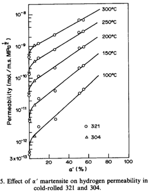
One reason I did not include stainless steel was there were many stainless steels and the hydrogen permeation rates were different, especially so between austenitic (FCC) steels and ferritic steels (BCC). Another issue was oxidation. All stainless steels are oxidized, and it affect H2 permeation a lot. You can decrease the hydrogen permeation rate significantly by oxidation, or by surface nitriding, etc (my company will even provide this service). Yet another issue is cold work. When  an austenitic stainless steel is worked — rolled or drawn — some Austinite (FCC) material transforms to Martisite (a sort of stretched BCC). Even a small amount of martisite causes an order of magnitude difference in the permeation rate, as shown below. For better or worse, after 20 years, I’m now ready to address H2 in stainless steel, or as ready as I’m likely to be.

Hydrogen permeation data for SS 340 and SS 321.

Hydrogen permeation in SS 340 and SS 321. Cold work affects H2 permeation more than the difference between 304 and 321; Sun Xiukui, Xu Jian, and Li Yiyi, 1989

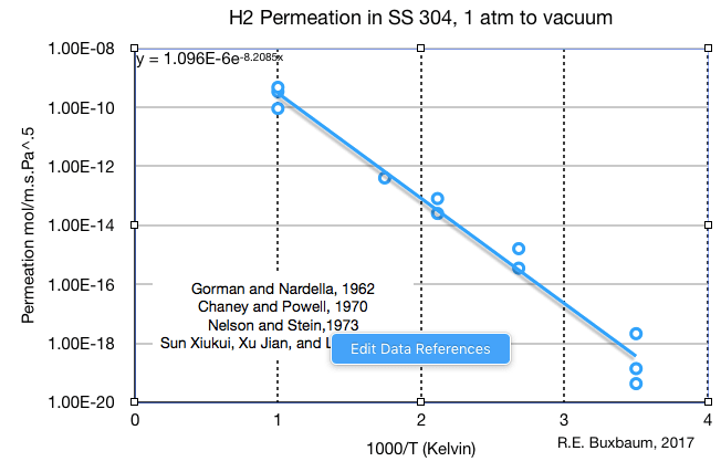
The first graph I’d like to present, above, is a combination of four research groups’ data for hydrogen transport in clean SS 304, the most common stainless steel in use today. SS 304 is a ductile, austenitic (FCC), work hardening, steel of classic 18-8 composition (18% Cr, 8% Ni). It shares the same basic composition with SS 316, SS 321 and 304L only differing in minor components. The data from four research groups shows a lot of scatter: a factor of 5 variation at high temperature, 1000 K (727 °C), and almost two orders of magnitude variation (factor of 50) at room temperature, 13°C. Pressure is not a factor in creating the scatter, as all of these studies were done with 1 atm, 100 kPa hydrogen transporting to vacuum.

The two likely reasons for the variation are differences in the oxide coat, and differences in the amount of cold work. It is possible these are the same explanation, as a martensitic phase might increase H2 permeation by introducing flaws into the oxide coat. As the graph at left shows, working these alloys causes more differences in H2 permeation than any difference between alloys, or at least between SS 304 and SS 321. A good equation for the permeation behavior of SS 304 is:

P (mol/m.s.Pa1/2) = 1.1 x10⁻⁶ exp (-8200/T).      (H2 in SS-304)

Because of the song influence of cold work and oxidation, I’m of the opinion that I get a slightly different, and better equation if I add in permeation data from three other 18-8 stainless steels:

P (mol/m.s.Pa1/2) = 4.75 x10-7 exp (-7880/T).     (H2 in annealed SS-304, SS-316, SS-321)

Screen Shot 2017-12-16 at 10.37.37 PM

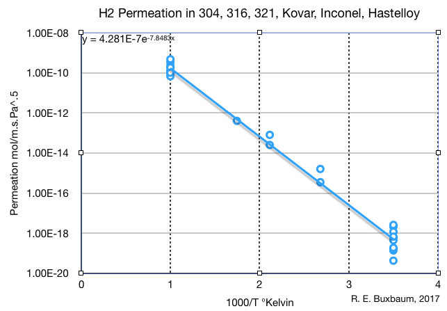
Hydrogen permeation through several common stainless steels, as well as Inocnel and Hastelloy

Though this result is about half of the previous at high temperature, I would trust it better, at least for annealed SS-304, and also for any annealed austenitic stainless steel. Just as an experiment, I decided to add a few nickel and cobalt alloys to the mix, and chose to add data for inconel 600, 625, and 718; for kovar; for Hastelloy, and for Fe-5%Si-5%Ge, and SS4130. At left, I pilot all of these on one graph along with data for the common stainless steels. To my eyes the scatter in the H2 permeation rates is indistinguishable from that SS 304 above or in the mixed 18-8 steels (data not shown). Including these materials to the plot decreases the standard deviation a bit to a factor of 2 at 1000°K and a factor of 4 at 13°C. Making a least-square analysis of the data, I find the following equation for permeation in all common FCC stainless steels, plus Inconels, Hastelloys and Kovar:

P (mol/m.s.Pa1/2) = 4.3 x10⁻⁷ exp (-7850/T).

This equation is near-identical to the equation above for mixed, 18-8 stainless steel. I would trust it for annealed or low carbon metal (SS-304L) to a factor of 2 accuracy at high temperatures, or a factor of 4 at low temperatures. Low carbon reduces the tendency to form Martinsite. You can not use any of these equations for hydrogen in ferritic (BCC) alloys as the rates are different, but this is as good as you’re likely to get for basic austenitc stainless and related materials. If you are interested in the effect of cold work, here is a good reference. If you are bothered by the square-root of pressure driving force, it’s a result of entropy: hydrogen travels in stainless steel as dislocated H atoms and the dissociation H2 –> 2 H leads to the square root.

Robert Buxbaum, December 17, 2017. My business, REB Research, makes hydrogen generators and purifiers; we sell getters; we consult on hydrogen-related issues, and will (if you like) provide oxide (and similar) permeation barriers.

The hydrogen jerrycan

Here’s a simple invention, one I’ve worked on off-and-on for years, but never quite built. I plan to work on it more this summer, and may finally build a prototype: it’s a hydrogen Jerry can. The need to me is terrifically obvious, but the product does not exist yet.

To get a view of the need, imagine that it’s 5-10 years in the future and you own a hydrogen, fuel cell car. You’ve run out of gas on a road somewhere, per haps a mile or two from the nearest filling station, perhaps more. You make a call to the AAA road-side service and they show up with enough hydrogen to get you to the next filling station. Tell me, how much hydrogen did they bring? 1 kg, 2 kg, 5 kg? What did the container look like? Is there one like it in your garage?

The original, German "Jerry" can. It was designed at the beginning of WWII to help the Germans to overrun Europe.

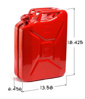
The original, German “Jerry” can. It was designed at the beginning of WWII to help the Germans to overrun Europe. I imagine the hydrogen version will be red and roughly these dimensions, though not quite this shape.

I figure that, in 5-10 years these hydrogen containers will be so common that everyone with a fuel cell car will have one, somewhere. I’m pretty confident too that hydrogen cars are coming soon. Hydrogen is not a total replacement for gasoline, but hydrogen energy provides big advantages in combination with batteries. It really adds to automotive range at minimal cost. Perhaps, of course this is wishful thinking as my company makes hydrogen generators. Still it seems worthwhile to design this important component of the hydrogen economy.

I have a mental picture of what the hydrogen delivery container might look like based on the “Jerry can” that the Germans (Jerrys) developed to hold gasoline –part of their planning for WWII. The story of our reverse engineering of it is worth reading. While the original can was green for camouflage, modern versions are red to indicate flammable, and I imagine the hydrogen Jerry will be red too. It must be reasonably cheap, but not too cheap, as safety will be a key issue. A can that costs $100 or so does not seem excessive. I imagine the hydrogen Jerry can will be roughly rectangular like the original so it doesn’t roll about in the trunk of a car, and so you can stack a few in your garage, or carry them conveniently. Some folks will want to carry an extra supply if they go on a long camping trip. As high-pressure tanks are cylindrical, I imagine the hydrogen-jerry to be composed of two cylinders, 6 1/2″ in diameter about. To make the rectangular shape, I imagine the cylinders attached like the double pack of a scuba diver. To match the dimensions of the original, the cylinders will be 14″ to 20″ tall.

I imagine that the hydrogen Jerry can will have at least two spouts. One spout so it can be filled from a standard hydrogen dispenser, and one so it can be used to fill your car. I suspect there may be an over-pressure relief port as well, for safety. The can can’t be too heavy, no more than 33 lbs, 15 kg when full so one person can handle it. To keep the cost and weight down, I imagine the product will be made of marangeing steel wrapped in kevlar or carbon fiber. A 20 kg container made of these materials will hold 1.5 to 2 kg of hydrogen, the equivalent of 2 gallons of gasoline.

I imagine that the can will have at least one handle, likely two. The original can had three handles, but this seems excessive to me. The connection tube between two short cylinders could be designed to serve as one of the handles. For safety, the Jerrycan should have a secure over-seal on both of the fill-ports, ideally with a safety pin latch minimize trouble in a crash. All the parts, including the over- seal and pin, should be attached to the can so that they are not easily lost. Do you agree? What else, if anything, do you imagine?

Robert Buxbaum, February 26, 2017. My company, REB Research, makes hydrogen generators and purifiers.

New REB hydrogen generator for car fueling, etc.

One of my favorite invention ideas, one that I’ve tried to get the DoE to fund, is a membrane hydrogen generator where the waste gas is burnt to heat the reactor. The result should be exceptional efficiency, low-cost, low pollution, and less infrastructure needs. Having failed to interest the government, I’ve gone and built one on my own dime. That’s me on the left, with Shua Spirka, holding the new core module (reactor, boiler, purifier and purifier) sized for personal car fueling.

Me and Shua and our new hydrogen generator core

Me and Shua and our new hydrogen generator core

The core just arrived from the shop last week, now we have to pumps and heat exchangers. As with our current products, the hydrogen is generated from methanol water, and extracted 99.99999% pure by diffusion through a metal membrane. This core fit in a heat transfer pot (see lower right) and the pot sits on a burner for the waste gas. Control is tricky, but I think I’ve got it. If it all works like it’s supposed to, the combination should be 80-90% energy-efficient, delivering about 75 slpm, 9 kg per day. That’s the same output as our largest current electrically heated generators, with a much lower infrastructure cost. The output should be enough to fuel one hydrogen-powered automobile per day, or keep a small fleet of plug-in, hydrogen-hybrids running continuously.

Hydrogen automobiles have a lot of advantages over Tesla-type electric automobiles. I’ll tell you how the thing works as soon as we set it up and test it. Right now, we’ve got other customers and other products to make.

Robert Buxbaum, February 18, 2016. If someone could supply a good hydrogen compressor, and a good fuel cell, that would be most welcome. Someone who can supply that will be able to ride in a really excellent cart of the future at this year’s July 4th parade.

Chemical engineers and boilers, ‘I do anything’

One of the problems I run into trying to hire chemical engineers is that their background is so varied that they imagine they can do anything. Combine this with a willingness to try to do anything, and the job interview can go like this.

Me: You have a great resume. I suppose you know that our company is a leader in hydrogen engineering (in my case). Tell me, what do you see yourself doing at our company?

Engineer: I don’t know. I do anything and everything.

Me: That covers a lot of ground. Is there something that you do particularly well, or that you would particularly like to do here?

Engineer.: Anything, really.

Me: Do you see yourself making coffee?

Engineer: I could do that, but was thinking of something with more … responsibility.

Me: OK. Could you design and build a 5 kW, gas-fired boiler?

Engineer: Himm. How much coffee did you say you guys drink?

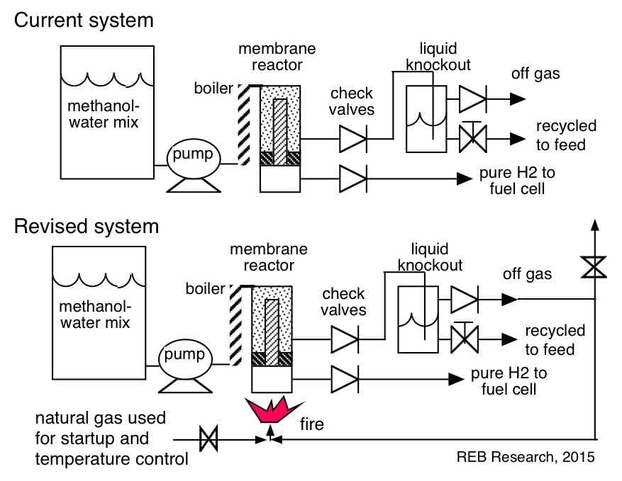
Current version of our H2 generators (simplified) and the combustion-heated modification I'm working on.

Current version of our H2 generators (simplified) and the combustion-heated modification I’m working on.

Not quite where I was going with that. The relevance of this joke is that I’m finally getting around to redesigning our hydrogen generators so that they are heated by waste-gas combustion instead of electricity. That was the plan originally, and it appears in almost all of my patents. But electricity is so easy to deal with and control that all REB generators have been heated this way, even the largest.

The current and revised processes are shown in the figure at right. Our general process is to make ultra pure hydrogen from methanol and water in one step by the following reaction:

CH3OH + H2O –> CO2  + 3 H2.

done in a membrane reactor (see advantages). My current thought is to make the first combustion heated hydrogen generator have an output about 2/3 as large as our largest. That is, to produce 100 scfh, or 50 slpm, or 6 kg of H2/ day. This could be advantageous for people trying to fuel fork lifts or a hybrid, fuel cell car; a car could easily carry 12 kg of hydrogen, allowing it to go an extra 300 miles.

The generator with this output will need a methanol-water feed rate of about 2/3 gal per hour (about 80¢/worth pre hour), and will need a heat rate of 2.5 to 3 kW. A key design issue is that I have to be sure not to extract too much energy value from the feed because, if there’s not enough energy in the waste gas, the fire could go out. That is, nearly pure CO2 doesn’t burn. Alternately, if there is too much flow to the flame or too much energy content, there might be over-heating. In order to avoid the flame going out, I have a pilot flame that turns off the flow if it goes out. I also plan to provide 30% or so of the reactor heat about 800 W, by burning non-wast gas, natural gas in this iteration. My plan is to use this flow to provide most of the temperature control, but to provide secondary control by (and safety) by venting some of the off-gas if the reactor gets hotter than a set limit. Early experiments suggest it should work.

The business side of this is still unknown. Perhaps this would provide military power or cabins in the woods. Perhaps ship-board auxiliary power or balloons, or hydrogen fueling stations, or perhaps it will be used for chemical applicationsWith luck, it’ll sell to someone who needs hydrogen.

Robert E. Buxbaum. December 4, 2015. By the way, hydrogen isn’t as flammable as you might think.

Air swimmer at REB Research

Birds got to swim and fish got to fly. Gonna love that hydrogen till the day I die. Here’s a movie of our hydrogen-filled air swimmer, a fish-blimp at REB Research. My hope is that this thing will help us sell hydrogen generators — perhaps to folks who fly military balloons, or those who fly hydrogen balloons for sport. On the other hand, the swimmer is a lot of fun to play with — and I got to show it off to a first grade class!

Aside from balloon fliers, military and otherwise, the sort of customers I’d hoped to attract were those building fueling stations for fuel cell cars or drone airplanes, and those running multiple gas chromatographs or adding hydrogen to car or diesel engine. Even small amounts of hydrogen added to a standard engine will reduce pollution significantly, add raise mileage too: a plus for a company like VW.

Dr. Robert E. Buxbaum, December 2, 2015. I should mention that hydrogen balloons are no where near as unsafe as people think. Here’s a movie I made of lighting a hydrogen filled balloon with a cigar.

my electric cart of the future

Buxbaum and Sperka cart of future

Buxbaum and Sperka show off the (shopping) cart of future, Oak Park parade July 4, 2015.

A Roman chariot did quite well with only 1 horse-power, while the average US car requires 100 horses. Part of the problem is that our cars weigh more than a chariot and go faster, 80 mph vs of 25 mph. But most city applications don’t need all that weight nor all of that speed. 20-25 mph is fine for round-town errands, and should be particularly suited to use by young drivers and seniors.

To show what can be done with a light vehicle that only has to go 20 mph, I made this modified shopping cart, and fitted it with a small, 1 hp motor. I call it the cart-of the future and paraded around with it at our last 4th of July parade. It’s high off the ground for safety, reasonably wide for stability, and has the shopping cart cage and seat-belts for safety. There is also speed control. We went pretty slow in the parade, but here’s a link to a video of the cart zipping down the street at 17.5 mph.

In the 2 months since this picture was taken, I’ve modified the cart to have a chain drive and a rear-wheel differential — helpful for turning. My next modification, if I get to it, will be to switch to hydrogen power via a fuel cell. One of the main products we make is hydrogen generators, and I’m hoping to use the cart to advertise the advantages of hydrogen power.

Robert E. Buxbaum, August 28, 2015. I’m the one in the beige suit.

My latest invention: improved fuel cell reformer

Last week, I submitted a provisional patent application for an improved fuel reformer system to allow a fuel cell to operate on ordinary, liquid fuels, e.g. alcohol, gasoline, and JP-8 (diesel). I’m attaching the complete text of the description, below, but since it is not particularly user-friendly, I’d like to add a small, explanatory preface. What I’m proposing is shown in the diagram, following. I send a hydrogen-rich stream plus ordinary fuel and steam to the fuel cell, perhaps with a pre-reformer. My expectation that the fuel cell will not completely convert this material to CO2 and water vapor, even with the pre-reformer. Following the fuel cell, I then use a water-gas shift reactor to convert product CO and H2O to H2 and CO2 to increase the hydrogen content of the stream. I then use a semi-permeable membrane to extract the waste CO2 and water. I recirculate the hydrogen and the rest of the water back to the fuel cell to generate extra power, prevent coking, and promote steam reforming. I calculate the design should be able to operate at, perhaps 0.9 Volt per cell, and should nearly double the energy per gallon of fuel compared to ordinary diesel. Though use of pure hydrogen fuel would give better mileage, this design seems better for some applications. Please find the text following.

Use of a Water-Gas shift reactor and a CO2 extraction membrane to improve fuel utilization in a solid oxide fuel cell system.

Inventor: Dr. Robert E. Buxbaum, REB Research, 12851 Capital St, Oak Park, MI 48237; Patent Pending.

Solid oxide fuel cells (SOFCs) have improved over the last 10 years to the point that they are attractive options for electric power generation in automobiles, airplanes, and auxiliary power supplies. These cells operate at high temperatures and tolerate high concentrations of CO, hydrocarbons and limited concentrations of sulfur (H2S). SOFCs can operate on reformate gas and can perform limited degrees of hydrocarbon reforming too – something that is advantageous from the stand-point of fuel logistics: it’s far easier to transport a small volume of liquid fuel that it is a large volume of H2 gas. The main problem with in-situ reforming is the danger of coking the fuel cell, a problem that gets worse when reforming is attempted with the more–desirable, heavier fuels like gasoline and JP-8. To avoid coking the fuel cell, heavier fuels are typically reforming before hand in a separate reactor, typically by partial oxidation at auto-thermal conditions, a process that typically adds nitrogen and results in the inability to use the natural heat given off by the fuel cell. Steam reforming has been suggested as an option (Chick, 2011) but there is not enough heat released by the fuel cell alone to do it with the normal fuel cycles.

Another source of inefficiency in reformate-powered SOFC systems is basic to the use of carbon-containing fuels: the carbon tends to leave the fuel cell as CO instead of CO2. CO in the exhaust is undesirable from two perspectives: CO is toxic, and quite a bit of energy is wasted when the carbon leaves in this form. Normally, carbon can not leave as CO2 though, since CO is the more stable form at the high temperatures typical of SOFC operation. This patent provides solutions to all these problems through the use of a water-gas shift reactor and a CO2-extraction membrane. Find a drawing of a version of the process following.

RE. Buxbaum invention: A suggested fuel cycle to allow improved fuel reforming with a solid oxide fuel cell

RE. Buxbaum invention: A suggested fuel cycle to allow improved fuel reforming with a solid oxide fuel cell

As depicted in Figure 1, above, the fuel enters, is mixed with steam or partially boiled water, and heated in the rectifying heat exchanger. The hot steam + fuel mix then enters a steam reformer and perhaps a sulfur removal stage. This would be typical steam reforming except for a key difference: the heat for reforming comes (at least in part) from waste heat of the SOFC. Normally speaking there would not be enough heat, but in this system we add a recycle stream of H2-rich gas to the fuel cell. This stream, produced from waste CO in a water-gas shift reactor (the WGS) shown in Figure 1. This additional H2 adds to the heat generated by the SOFC and also adds to the amount of water in the SOFC. The net effect should be to reduce coking in the fuel cell while increasing the output voltage and providing enough heat for steam reforming. At least, that is the thought.

SOFCs differ from proton conducting FCS, e.g. PEM FCs, in that the ion that moves is oxygen, not hydrogen. As a result, water produced in the fuel cell ends up in the hydrogen-rich stream and not in the oxygen stream. Having this additional water in the fuel stream of the SOFC can promote fuel reforming within the FC. This presents a difficulty in exhausting the waste water vapor in that a means must be found to separate it from un-combusted fuel. This is unlike the case with PEM FCs, where the waste water leaves with the exhaust air. Our main solution to exhausting the water is the use of a membrane and perhaps a knockout drum to extract it from un-combusted fuel gases.

Our solution to the problem of carbon leaving the SOFC as CO is to react this CO with waste H2O to convert it to CO2 and additional H2. This is done in a water gas shift reactor, the WGS above. We then extract the CO2 and remaining, unused water through a CO2- specific membrane and we recycle the H2 and unconverted CO back to the SOFC using a low temperature recycle blower. The design above was modified from one in a paper by PNNL; that paper had neither a WGS reactor nor a membrane. As a result it got much worse fuel conversion, and required a high temperature recycle blower.

Heat must be removed from the SOFC output to cool it to a temperature suitable for the WGS reactor. In the design shown, the heat is used to heat the fuel before feeding it to the SOFC – this is done in the Rectifying HX. More heat must be removed before the gas can go to the CO2 extractor membrane; this heat is used to boil water for the steam reforming reaction. Additional heat inputs and exhausts will be needed for startup and load tracking. A solution to temporary heat imbalances is to adjust the voltage at the SOFC. The lower the voltage the more heat will be available to radiate to the steam reformer. At steady state operation, a heat balance suggests we will be able to provide sufficient heat to the steam reformer if we produce electricity at between 0.9 and 1.0 Volts per cell. The WGS reactor allows us to convert virtually all the fuel to water and CO2, with hardly any CO output. This was not possible for any design in the PNNL study cited above.

The drawing above shows water recycle. This is not a necessary part of the cycle. What is necessary is some degree of cooling of the WGS output. Boiling recycle water is shown because it can be a logistic benefit in certain situations, e.g. where you can not remove the necessary CO2 without removing too much of the water in the membrane module, and in mobile military situations, where it’s a benefit to reduce the amount of material that must be carried. If water or fuel must be boiled, it is worthwhile to do so by cooling the output from the WGS reactor. Using this heat saves energy and helps protect the high-selectivity membranes. Cooling also extends the life of the recycle blower and allows the lower-temperature recycle blowers. Ideally the temperature is not lowered so much that water begins to condense. Condensed water tends to disturb gas flow through a membrane module. The gas temperatures necessary to keep water from condensing in the module is about 180°C given typical, expected operating pressures of about 10 atm. The alternative is the use of a water knockout and a pressure reducer to prevent water condensation in membranes operated at lower temperatures, about 50°C.

Extracting the water in a knockout drum separate from the CO2 extraction has the secondary advantage of making it easier to adjust the water content in the fuel-gas stream. The temperature of condensation can then be used to control the water content; alternately, a separate membrane can extract water ahead of the CO2, with water content controlled by adjusting the pressure of the liquid water in the exit stream.

Some description of the membrane is worthwhile at this point since a key aspect of this patent – perhaps the key aspect — is the use of a CO2-extraction membrane. It is this addition to the fuel cycle that allows us to use the WGS reactor effectively to reduce coking and increase efficiency. The first reasonably effective CO2 extraction membranes appeared only about 5 years ago. These are made of silicone polymers like dimethylsiloxane, e.g. the Polaris membrane from MTR Inc. We can hope that better membranes will be developed in the following years, but the Polaris membrane is a reasonably acceptable option and available today, its only major shortcoming being its low operating temperature, about 50°C. Current Polaris membranes show H2-CO2 selectivity about 30 and a CO2 permeance about 1000 Barrers; these permeances suggest that high operating pressures would be desirable, and the preferred operation pressure could be 300 psi (20 atm) or higher. To operate the membrane with a humid gas stream at high pressure and 50°C will require the removal of most of the water upstream of the membrane module. For this, I’ve included a water knockout, or steam trap, shown in Figure 1. I also include a pressure reduction valve before the membrane (shown as an X in Figure 1). The pressure reduction helps prevent water condensation in the membrane modules. Better membranes may be able to operate at higher temperatures where this type of water knockout is not needed.

It seems likely that, no matter what improvements in membrane technology, the membrane will have to operate at pressures above about 6 atm, and likely above about 10 atm (upstream pressure) exhausting CO2 and water vapor to atmosphere. These high pressures are needed because the CO2 partial pressure in the fuel gas leaving the membrane module will have to be significantly higher than the CO2 exhaust pressure. Assuming a CO2 exhaust pressure of 0.7 atm or above and a desired 15% CO2 mol fraction in the fuel gas recycle, we can expect to need a minimum operating pressure of 4.7 atm at the membrane. Higher pressures, like 10 or 20 atm could be even more attractive.

In order to reform a carbon-based fuel, I expect the fuel cell to have to operate at 800°C or higher (Chick, 2011). Most fuels require high temperatures like this for reforming –methanol being a notable exception requiring only modest temperatures. If methanol is the fuel we will still want a rectifying heat exchanger, but it will be possible to put it after the Water-Gas Shift reactor, and it may be desirable for the reformer of this fuel to follow the fuel cell. When reforming sulfur-containing fuels, it is likely that a sulfur removal reactor will be needed. Several designs are available for this; I provide references to two below.

The overall system design I suggest should produce significantly more power per gm of carbon-based feed than the PNNL system (Chick, 2011). The combination of a rectifying heat exchange, a water gas reactor and CO2 extraction membrane recovers chemical energy that would otherwise be lost with the CO and H2 bleed steam. Further, the cooling stage allows the use of a lower temperature recycle pump with a fairly low compression ratio, likely 2 or less. The net result is to lower the pump cost and power drain. The fuel stream, shown in orange, is reheated without the use of a combustion pre-heater, another big advantage. While PNNL (Chick, 2011) has suggested an alternative route to recover most of the chemical energy through the use of a turbine power generator following the fuel cell, this design should have several advantages including greater reliability, and less noise.

Claims:

1.   A power-producing, fuel cell system including a solid oxide fuel cell (SOFC) where a fuel-containing output stream from the fuel cell goes to a regenerative heat exchanger followed by a water gas shift reactor followed by a membrane means to extract waste gases including carbon dioxide (CO2) formed in said reactor. Said reactor operating a temperatures between 200 and 450°C and the extracted carbon dioxide leaving at near ambient pressure; the non-extracted gases being recycled to the fuel cell.

Main References:

The most relevant reference here is “Solid Oxide Fuel Cell and Power System Development at PNNL” by Larry Chick, Pacific Northwest National Laboratory March 29, 2011: http://www.energy.gov/sites/prod/files/2014/03/f10/apu2011_9_chick.pdf. Also see US patent  8394544. it’s from the same authors and somewhat similar, though not as good and only for methane, a high-hydrogen fuel.

Robert E. Buxbaum, REB Research, May 11, 2015.

How do technology companies sell stuff?

As the owner of a technology company, REB Research, hydrogen generators and hydrogen purifiers, I spend a fair amount of time trying to sell my stuff, and wondering how other companies connect to potential customers and sell to them. Sales is perhaps the most important area of business success, the one that makes or breaks most businesses — but it was sadly ignored in my extensive college education. Business books are hardly better: they ignore the salesmen (and women); you’re left to imagine sales and profit came of themselves by the insight of the great leader. The great, successful internet companies are applauded for giving away services, and the failed interned companies are barely mentioned. And hardly any book mentions smaller manufacturing businesses, like mine.

So here are some sales thoughts: things I tried, things that worked, and didn’t. I started my company, REB Research, about 20 years ago as a professor at Michigan State University. I figured I knew more about hydrogen purifiers than most of my colleagues, and imagined this knowledge would bring me money (big mistake: I needed customers and profitable sales). My strategy was to publish papers on hydrogen and get some patents as a way to build credibility (worked reasonably well: I write well, do research well, and I’m reasonably inventive). Patents might have been a better strategy if I had not then allowed my patents to be re-written by lawyers. I built the company. while still a professor (a good idea, I think).

When I realized I needed sales, I decided to use trade fairs, conferences, and ads as the big companies did. Most of my budget went for ads in The Thomas Register of American Manufacturing, a fantastically large compendium of who did or sold what (it worked OK, but was since rendered obsolete by the internet). I bought $1500 worth of ads, and got 2 small lines plus a 1/8 page. That’s where I got my sales until the internet cam along. In retrospect, I suspect I should have bought more ads.

William Hamilton cartoon from the new-yorker. I sure wish I could make deals.

William Hamilton cartoon from the new-yorker.

My other big expense was trade fairs. Many big companies sold at trade fairs, events that are widely attended in my field. Sorry to say, I never found customers at these fairs, even when the fairs were dedicated to hydrogen, everyone who’d come by was was selling, and no one was buying, as best I could tell.Somehow, my bigger competitors (also at the fairs) seemed to get interest but I’m not sure if they got sales there. They seem to find sales somewhere, though. Is it me? Am I at the wrong fairs, or are fairs just a scam where no one wins but the organizers? I don’t know. Last month, I spent $2000 for a booth in Ann Arbor, MI, including $350 for inclusion into the promoter’s book and $400 for hand-out literature. As with previous events, few people came by and none showed anything like interest, I got no e-mail addresses and no sales. Some hungry students wandered the stalls for food and freebees, but there was not one person with money in his/her pocket and a relevant project to spend it on. I doubt anyone read the literature they took.

To date, virtually all of my sales have come from the internet. I got on the internet early, and that has helped my placement in Google. I’ve never bought a google ad, but this may change. Instead I was lucky. About 20 years ago, 1994?, I attended a conference at Tufts on membrane reactors, and stayed at a bed-and-breakfast. After the conference let out, the owner of the BnB suggested I visit something that was new at Harvard; a cyber cafe, the second one in the US. They had Macintosh computers and internet explorer a year before the company went public. I was hooked, went home, learned html, and wrote a web-site. I bought my domain name shortly thereafter.

The problem, I don’t know the next big thing. Twitter? Facebook? LinkedIn? I’m on 2 of these 3, and have gotten so sales from social media. I started a blog (you’re reading it), but I still wonder, why are the bigger companies selling more? The main difference I see is they attend a lot more product fairs than I do, have slicker web-sties (not very good ones, I think), and they do print advertising. Perhaps they match their fairs to their products better, or have a broader range of products. People need to see my products somewhere, but where? My latest idea: this week I bought HydrogenPurifier.com. Send me advice, or wish me luck.

Robert E. Buxbaum, flailing entrepreneur, September 10, 2014. Here’s a feedback form, the first time I’m adding one.