Category Archives: Science: Physics, Astronomy, etc.

If the wall with Mexico were covered in solar cells

As a good estimate, it will take about 130,000 acres of solar cells to deliver the power of a typical nuclear facility, 26 TWhr/year. Since Donald Trump has proposed covering his wall with Mexico with solar cells, I came to wonder how much power these cells would produce, and how much this wall might cost. Here goes.

Lets assume that Trump’s building a double wall on a strip of land one chain (66 feet) wide, with a 2 lane road between. Many US roads are designed in chain widths, and a typical, 2 lane road is 1/2 chain wide, 33 feet, including its shoulders. I imagine that each wall is slanted 50° as is typical with solar cells, and that each is 15 to 18 feet high for a good mix of power and security. Since there are 10 square chains to an acre, and 80 chains to a mile we find that it would take 16,250 miles of this to produce 26 TWhr/year. The proposed wall is only about 1/10 this long, 1,600 miles or so, so the output will be only about 1/10 as much, 2.6 TWhr/year, or 600 MW per average daylight hour. That’s not insignificant power — similar to a good-size coal plant. If we aim for an attractive wall, we might come to use Elon Musk’s silica-coated solar cells. These cost $5/Watt or $3 Billion total. Other cells are cheaper, but don’t look as nice or seem as durable. Obama’s, Ivanpah solar farm, a project with durability problems, covers half this area, is rated at 370 MW, and cost $2.2 Billion. It’s thus rated to produce slightly over half the power of the wall, at a somewhat higher price, $5.95/Watt.

Elon Musk with his silica solar panels.

Elon Musk with his, silica-coated, solar wall panels. They don’t look half bad and should be durable.

It’s possible that the space devoted to the wall will be wider than 66 feet, or that the length will be less than 1600 miles, or that we will use different cells that cost more or less, but the above provides a good estimate of design, price, and electric output. I see nothing here to object to, politically or scientifically. And, if we sell Mexico the electricity at 11¢/kWhr, we’ll be repaid $286 M/year, and after 12 years or so, Republicans will be able to say that Mexico paid for the wall. And the wall is likely to look better than the Ivanpah site, or a 20-year-old wind farm.

As a few more design thoughts, I imagine an 8 foot, chain-link fence on the Mexican side of the wall, and imagine that many of the lower solar shingles will be replaced by glass so drivers will be able to see the scenery. I’ve posited that secure borders make a country. Without them, you’re a tribal hoard. I’ve also argued that there is a pollution advantage to controlling imports, and an economic advantage as well, at least for some. For comparison, recent measurement of the Great Wall of China shows it to be 13,170 miles long, 8 times the length of Trump’s wall with China.

Dr. Robert E. Buxbaum, June 14, 2017.

A clever, sorption-based, hydrogen compressor

Hydrogen-powered fuel cells provide weight and cost advantages over batteries, important e.g. for drones and extended range vehicles, but they require highly compressed hydrogen and it’s often a challenge compressing the hydrogen. A large-scale solution I like is pneumatic compression, e.g. this compressor. One would combine it with a membrane reactor hydrogen generator, to fill tanks for fuel cells. The problem is that this pump is somewhat complex, and would likely add air impurities to the hydrogen. I’d now like to describe a different, very clever hydrogen pump, one that suited to smaller outputs, but adds no impurities and and provides very high pressure. It operates by metallic hydride sorption at low temperature, followed by desorption at high temperature.

Hydride sorption -desorption pressures vs temperature.

Hydride sorption -desorption pressures vs temperature, from Dhinesh et al.

The metal hydriding reaction is M + nH2 <–> MH2n. Where M is a metal or metallic alloy and MH2n is the hydride. While most metals will undergo this reaction at some appropriate temperature and pressure, the materials of practical interest are exothermic hydrides that is hydrides that give off heat on hydriding. They also must undergo a nearly stoichiometric absorption or desorption reaction at reasonable temperatures and pressures. The plot at right presents the plateau pressure for hydrogen absorption/ desorption in several, exothermic metal hydrides. The most attractive of these are shown in the red box near the center. These sorb or desorb between 1 and 10 atmospheres and 25 and 100 °C.

In this plot, the slope of the sorption line is proportional to the heat of sorption. The most attractive materials for this pump are the ones in the box (or near) with a high slope to the line implying a high heat of sorption. A high heat of sorption means you can get very high compression without too much of a temperature swing.

To me, NaAlH4 appears to be the best of the materials. Though I have not built a pump yet with this material, I’d like to. It certainly serves as a good example for how the pump might work. The basic reaction is:

NaAl + 2H2 <–> NaAlH4

suggesting that each mol of NaAl material (50g) will absorb 2 mols of hydrogen (44.8 std liters). The sorption line for this reaction crosses the 1 atm horizontal line at about 30°C. This suggests that sorption will occur at 1 am and normal room temperature: 20-25°C. Assume the pump contains 100 g of NaAl (2.0 mols). Under ideal conditions, these 100g will 4 mols of hydrogen gas, about 90 liters. If this material in now heated to 226°C, it will desorb the hydrogen (more like 80%, 72 liters) at a pressure in excess of 100 atm, or 1500 psi. The pressure line extends beyond the graph, but the sense is that one could pressure in the neighborhood of 5000 psi or more: enough to use filling the high pressure tank of a hydrogen-based, fuel cell car.

The problem with this pump for larger volume H2 users is time. It will take 2-3 hours to cycle the sober, that is, to absorb hydrogen at low pressure, to heat the material to 226°C, to desorb the H2 and cycle back to low temperature. At a pump rate of 72 liters in 2-3 hours, this will not be an effective pump for a fuel-cell car. The output, 72 liters is only enough to generate 0.12kWh, perhaps enough for the tank of a fuel cell drone, or for augmenting the mpg of gasoline automobiles. If one is interested in these materials, my company, REB Research will be happy to manufacture some in research quantities (the prices blow are for materials cost, only I will charge significantly more for the manufactured product, and more yet if you want a heater/cooler system).

Properties of Metal Hydride materials; Dhanesh Chandra,* Wen-Ming Chien and Anjali Talekar, Material Matters, Volume 6 Article 2

Properties of Metal Hydride materials; Dhanesh Chandra,* Wen-Ming Chien and Anjali Talekar, Material Matters, Volume 6 Article 2

One could increase the output of a pump by using more sorbent, perhaps 10 kg distributed over 100 cells. With this much sorbent, you’ll pump 100 times faster, enough to take the output of a fairly large hydrogen generator, like this one from REB. I’m not sure you get economies of scale, though. With a mechanical pump, or the pneumatical pump,  you get an economy of scale: typically it costs 3 times as much for each 10 times increase in output. For the hydride pump, a ten times increase might cost 7-8 times as much. For this reason, the sorption pump lends itself to low volume applications. At high volume, you’re going to want a mechanical pump, perhaps with a getter to remove small amounts of air impurities.

Materials with sorption lines near the middle of the graph above are suited for long-term hydrogen storage. Uranium hydride is popular in the nuclear industry, though I have also provided Pd-coated niobium for this purpose. Materials whose graph appear at the far, lower left, titanium TiH2, can be used for permanent hydrogen removal (gettering). I have sold Pd-niobium screws for this application, and will be happy to provide other shapes and other materials, e.g. for reversible vacuum pumping from a fusion reactor.

Robert Buxbaum, May 26, 2017 (updated Apr. 4, 2022). 

Future airplane catapults may not be electric

President Trump got into Hot Water with the Navy this week for his suggestion that they should go “back to god-damn steam” for their airplane catapults as a cure for cost over-runs and delays with the Navy’s aircraft carriers. The Navy had chosen to go to a more modern catapult called EMALS (electromagnetic, aircraft launch system) based on a traveling coil and electromagnetic pulses. This EMAL system has cost $5 Billion in cost over-runs, has added 3 years to the program, and still doesn’t work well. In response to the president’s suggestion (explosion), the Navy did what the rest of Washington has done: blame Trump’s ignorance, e.g. here, in the Navy Times. Still, for what it’s worth, I think Trump’s idea has merit, especially if I can modify it a bit to suggest high pressure air (pneumatics) instead of high pressure steam.


Tests of the navy EMALS, notice that some launches go further than others; the problem is electronics, supposedly.

If you want to launch a 50,000 lb jet fighter at 5 g acceleration, you need to apply 250,000 lbs of force uniformly throughout the launch. For pneumatics, all that takes is 250 psi steam or air, and a 1000 square inch piston, about 3 feet in diameter. This is a very modest pressure and a quite modest size piston. A 50,000 lb object accelerated this way, will reach launch speed (130 mph) in 1.2 seconds. It’s very hard to get such fast or uniform acceleration with an electromagnetic coil since the motion of the coil always produces a back voltage. The electromagnetic pulses can be adjusted to counter this, but it’s not all that easy, as the Navy tests show. You have to know the speed and position of the airplane precisely to get it right, and have to adjust the firing of the pushing coils accordingly. There is no guarantee of smooth acceleration like you get with a piston, and the EMALS control circuit will always be vulnerable to electromagnetic and cyber attack. As things stand, the control system is thought to be the problem.

A piston is invulnerable to EM and cyber attack since, if worse comes to worse, the valves can be operated manually, as was done with steam-catapults throughout WWII. And pistons are very robust — far more robust than solenoid coils — because they are far less complex. As much force as you put on the plane, has to be put on the coil or piston. Thus, for 5 g acceleration, the coil or piston has to experience 250,000 lbs of horizontal force. That’s 3 million Newtons for those who like SI units (here’s a joke about SI units). A solid piston will have no problem withstanding 250,000 lbs for years. Piston steamships from the 50s are still in operation. Coils are far more delicate, and the life-span is likely to be short, at least for current designs. 

The reason I suggest compressed air, pneumatics, instead of steam is that air is not as hot and corrosive as steam. Also an air compressor can be located close to the flight deck, connected to the power center by electric wires. Steam requires long runs of steam pipes, a more difficult proposition. As a possible design, one could use a multi-stage, inter-cooled air compressor connected to a ballast tank, perhaps 5 feet in diameter x 100 feet long to guarantee uniform pressure. The ballast tank would provide the uniform pressure while allowing the use of a relatively small compressor, drawing less power than the EMALS. Those who’ve had freshman physics will be able to show that 5 g acceleration will get the plane to 130 mph in only 125 feet of runway. This is far less runway than the EMALS requires. For lighter planes or greater efficiency, one could shut off the input air before 120 feet and allow the remainder of the air to expand for 200 feet of the piston.

The same pistons could be used for capturing an airplane. It could start at 250 psi, dead-ended to the cylinder top. The captured airplane would push air back into the ballast tank, or the valve could be closed allowing pressure to build. Operated that way, the cylinder could stop the plane in 60 feet. You can’t do that with an EMAL. I should also mention that the efficiency of the piston catapult can be near 100%, but the efficiency of the EMALS will be near zero at the beginning of acceleration. Low efficiency at low speed is a problem found in all electromagnetic actuators: lots of electromagnetic power is needed to get things moving, but the output work,  ∫F dx, is near zero at low velocity. With EM, efficiency is high at only at one speed determined by the size of the moving coil; with pistons it’s high at all speeds. I suggest the Navy keep their EMALS, but only as a secondary system, perhaps used to launch drones until they get sea experience and demonstrate a real advantage over pneumatics.

Robert Buxbaum, May 19, 2017. The USS Princeton was the fanciest ship in the US fleet, with super high-tech cannons. When they mis-fired, it killed most of the cabinet of President Tyler. Slow and steady wins the arms race.

summer science: a toad or turtle terrarium

Here’s an easy summer science project, one I just made: a toad habitat. It’s similar to a turtle terrarium (I’ll show how to make that too). I’d made the turtle terrarium ten years ago for my 8-year-old daughter (here’s some advice I gave her on her 16th birthday).

For this project you’ll need: a large flower-pot, fish tank, or plastic clothes bin. You’ll need some dirt for the bottom, and a small plastic bin, jar, or Tupperware for toad (or turtle) transport. You’ll also need a smallish plastic dish or tub (~6″ by 1″ deep) to serve as a lake in the toad habitat. For the turtle version you don’t need the lake, but will need a rock or brick. And that’s all, besides your toad or turtle. The easy way to get your pet is to find one by a river. If that doesn’t work, go to a pet-store and get one that is native to your area of the country. Local fauna (fauna= animals) will be heartier and cheeper, and will allow you to keep your terrarium outside if you choose. Keeping my toad outside means he (or she) can catch bugs without me having to buy them all the time. It also seems more “natural” to study animals in their natural temperature cycles. I caught my toads three weeks ago, in mid April after the last frost — I plan to set one free in the fall –the other I gave away.

For my toad habitat, I used a large, old flower-pot that I had sitting outside my house. It is 21″ across at the top and 18″ tall. I put 6″ of dirt in it. six inches is deep enough for the toad to dig in, and it left 12″ of airspace — I don’t think the toad can jump a foot in the air to get out. I made sure the soil was muddy, and had worms. Toads seem to like mud and they eat worms. Toads drink water through their skin, and may not like chlorinated water. I also added some leaves and a small flower pot for shade, and put in some bits of fruit and some bugs, and planted a single plant. My hope was to develop a colony of ants and bugs for the toads to eat. I buried my plastic water bowl, my mini-lake, slightly below ground level with the top 1/2″ above. I then went off with my toad transport to catch a toad or three in the wetlands areas near me (I live in Oak Park, MI).

Some good toad hunting spots in Keego Harbor MI

Some good toad hunting spots in Keego Harbor MI

The first place I went was the banks of the Rouge river near Lawrence Tech. Sorry to say, the area showed no signs of toads, frogs, turtles, or even fish. There was an illegally connected drain, though — not good. I plan to bring the illegal grain up with the “Friends of the Rouge” (good group). I then went to an oak swamp on the Rouge. The area was beautiful and scenic, but there was no oxygen in the water and so no fish or toads; oxygen is important for the health of a river; without it, you’ve got  a swamp. I finally hit pay-dirt in Keego Harbor, MI, see map, a rural community 10 miles away from my home. In Keego harbor I found American toads aplenty: jumping all over, and big, hollow toad-mounds by the river. The locals were friendly too. Toad catching is a good conversation starter. I put two toads in my bin with some lake water and took them home to the terrarium, see movie.

My neighbor got the other toad and put him/her in a fish-tank terrarium in his bathroom. His terrarium has a screen on top with holes small enough to keep the toad and his food from escaping. He is feeding his toad meal worms, but I don’t have a movie. Apparently they like it.

I left my pot outside, as I mentioned, so my toad can catch insects that fly by, and spiders. My toad seems to like spiders. I also tried putting in wax-worms ($1 for 12). The good thing about wax worms is they move slowly, unlike crickets (crickets cost more and can jump out). My toad ate all 12 worms in 2 days. I have not put a lid on my pot yet. Perhaps that’s a mistake. My colony of bugs seems to be breeding fast enough to make up for escapees and eating, but perhaps that’s because the toad doesn’t eat many. A fellow at the pet store sold me ten small crickets for $3.00, but I don’t think the toad ate any before they escaped. See what your toad eats; it’s science. I think my toad is a female: it doesn’t vibrate or croak at night. Male toads vibrates and croak. Toads can be gender fluid, though; somethings two “female” toads will breed. Your job is to watch, enjoy, and perhaps learn something.

The main difference between this project, and the turtle terrarium I’d made is that the turtle terrarium was mostly water, with a brick, and this is mostly mud with a lake. I made the turtle terrarium in a laundry bin, a bigger environment, and flooded it except for the brick. I bought the turtles (a red-ears and a snapping) and fed it chicken bits and dandelion leaves. As with this terrarium, I kept the turtles outside through the spring, summer, and fall, but I brought the turtles in the winter. They lasted that way for about 8 years. Toads only live for 2-3 years, and mime may be a year or two old already. I won’t be too surprised if it croaks on my watch. For now, she seems safe and hoppy.

Robert Buxbaum, May 3, 2017. Here are some other science fair projects, chemical, and biological.

A very clever hydrogen pump

I’d like to describe a most clever hydrogen pump. I didn’t invent it, but it’s awfully cool. I did try to buy one from “H2 Pump,” a company that is now defunct, and I tried to make one. Perhaps I’ll try again. Here is a diagram.

Electrolytic membrane H2 pump

Electrolytic membrane H2 pump

This pump works as the reverse of of a PEM fuel cell. Hydrogen gas is on both sides of a platinum-coated, proton-conducting membrane — a fuel cell membrane. As in a PEM fuel cell, the platinum splits the hydrogen molecules into H atoms. An electrode removes electrons to form H+ ions on one side of the membrane; the electrons are on the other side of the membrane (the membrane itself is chosen to not conduct electricity). The difference from the fuel cell is that, for the pump you apply a energy (voltage) to drive hydrogen across the membrane, to a higher pressure side; in a fuel cell, the hydrogen goes on its own to form water, and you extract electric energy.

As shown, the design is amazingly simple and efficient. There are no moving parts except for the hydrogen itself. Not only do you pump hydrogen, but you can purify it as well, as most impurities (nitrogen, CO2) will not go through the membrane. Water does permeate the membrane, but for many applications, this isn’t a major impurity. The amount of hydrogen transferred per plate, per Amp-second of current is given by Faraday’s law, an equation that also shows up in my discussion of electrolysis, and of electroplating,

C= zFn.

Here, C is the current in Amp-seconds, z is the number or electrons transferred per molecule, in this case 2, F is Faraday’s constant, 96,800, n is the number of mols transferred.  If only one plate is used, you need 96,800 Amp-seconds per gram of hydrogen, 53.8 Amp hours per mol. Most membranes can operate at well at 1.5 Amp per cm2, suggesting that a 1.1 square-foot membrane (1000 cm2) will move about 1 mol per minute, 22.4 slpm. To reduce the current requirement, though not the membrane area requirement, one typically stacks the membranes. A 100 membrane stack would take 16.1 Amps to pump 22.4 slpm — a very manageable current.

The amount of energy needed per mol is related to the pressure difference via the difference in Gibbs energy, ∆G, at the relevant temperature.

Energy needed per mol is, ideally = ∆G = RT ln Pu/Pd.

where R is the gas constant, 8.34 Joules per mol, T is the absolute temperature, Kelvins (298 for a room temperature process), ln is the natural log, and Pu/Pd is the ratio of the upstream and downstream pressure. We find that, to compress 2 grams of hydrogen (one mol or 22.4 liters) to 100 atm (1500 psi) from 1 atm you need only 11400 Watt seconds of energy (8.34 x 298 x 4.61= 11,400). This is .00317 kW-hrs. This energy costs only 0.03¢ at current electric prices, by far the cheapest power requirement to pump this much hydrogen that I know of. The pump is surprisingly compact and simple, and you get purification of the hydrogen too. What could possibly go wrong? How could the H2 pump company fail?

One thing that I noticed went wrong when I tried building one of these was leakage at the seals. I found it uncommonly hard to make seals that held even 20 psi. I was using 4″ x 4″ membranes so 20 psi was the equivalent of 320 pounds of force. If I were to get 200 psi, there would have been 3200 lbs of force. I could never get the seals to stay put at anything more than 20 psi.

Another problem was the membranes themselves. The membranes I bought were not very strong. I used a wire-mesh backing, and a layer of steel behind that. I figured I could reach maybe 200 psi with this design, but didn’t get there. These low pressures limit the range of pump applications. For many applications,  you’d want 150-200 psi. Still, it’s an awfully cool pump,

Robert E. Buxbaum, February 17, 2017. My company, REB Research, makes hydrogen generators and purifiers. I’ve previously pointed out that hydrogen fuel cell cars have some dramatic advantages over pure battery cars.

Most flushable wipes aren’t flushable.

I’m a chemical engineer running for Oakland county water resources commissioner, and as the main job of the office is sewage, and as I’ve already written on the chemistry, I thought I might write about an aspect of the engineering. Specifically about toilet paper. Toilet paper is a remarkable product: it’s paper, compact and low in cost; strong enough to clean you, smooth on your bum, and beyond that, it will disintegrate in turbulent water so it doesn’t clog pipes. The trick to TP’s dry strength and wet-weakness, is that the paper pulp, wood cellulose, is pounded very thin, yet cast fluffy. For extra softness, the paper is typically coated with aloe or similar. Sorry to say, the same recipe does not work for wet-wipes, paper towels or kleenex (facial tissues); all of these products must have wet-strength, and this can cause problems with sewer clogs.

Patent 117355 for perforated toilet paper claimed it as an improved wrapping paper.

Patent 117,355 for perforated toilet paper on a roll. It’s claimed as an improved wrapping paper.

Before there was toilet paper, the world was a much sadder, and smellier place. Much of the world used sticks, stones, leaves, or corn cobs, and none of these did a particularly thorough job. Besides, none of these is particularly smooth, or particularly disposable, nor did it fall apart — not that most folks had indoor plumbing. Some rich Romans had plumbing, and these cleaned themselves with a small sponge on the end of a stick. They dipped the sponge end in water for each use. It was disgusting, but didn’t clog the pipes. I’ve seen this in use on a trip to Turkey 25 years ago — not in actual use, but the stick and sponge was there in a smelly bucket next to the hole in the ground that served as the commode.

The first reasonably modern toilet was invented in 1775 by Alexander Cummings, and by 1852 the first public flush toilets were available. The design looked pretty much like it looks today and the cost was 1¢. You got a towel and a shoe-shine too for that penny, but there was no toilet paper as such. Presumably one used a Roman sponge or some ordinary, standard paper. A popular wipe, back in the day was the Sears-Roebuck catalog. It came free to most homes and included a convenient hole in the corner allowing one to hang it in and outhouse or near the commode. It was rough on the bum, and didn’t fall apart. My guess is that it clogged the pipes too, for those who used it with flush toilets. The first toilet-specific paper wasn’t invented till 1859. Joseph Gayetty, an American, patented a product from pulverized hemp, a relatively soft fiber, softened further with aloe. This paper was softer than standard, and had less tendency to clog pipes.

Toilet paper has to be soft

Toilet paper is either touted to be soft or strong; Modern Charmin touts wet strength, while Cottonelle touts completeness of wipe: ‘go commando.”

The next great innovation was to make toilet paper as a perforated product on a roll. These novelties appear as US Patent #117,355 awarded to Seth Wheeler of Albany, NY 25 July 1871 (Wheeler also invented the classic roll toilet paper dispenser). Much of the sales pitch was that a cleaner bum would prevent the spread of cholera, typhoid, and other plagues and that is a legitimate claim. As the  market expanded, advertising followed. Some early brands touted their softness, others their strength. Facial tissues, e.g. Kleenex, were sold specifically as a soft TP-like product that does not fall apart when wet. Sorry to say, this tends to go along with clogged toilets; do not flush more than one kleenex down at a flush. Kleenex is made with the same short fibers and aloe as toilet paper, but it contains binders (glue) to give it wet-strength. My guess is that Charmin is made the same way and that it isn’t great on your plumbing.

Paper towels and most baby wipes are worse to flush than Kleenex. They are made with lots of binder and they really don’t fall apart in water. Paper towels should never be flushed, and neither should most baby wipes, even brands that claim to be ‘flushable.” When flushed, these items tend to soak up fat and become fat bergs – the bane of sewer workers everywhere. There is a class action law suit against flushable wipe companies, and New York City is pursuing legislation to prevent them from claiming to be flushable. Still, as with everything, there are better and worse moist-wipe options. “Cottonelle” brand by Kleenex, and Scott flushable wipes are the best currently. In a day or less they will dissolve in water. These products are made with binders like kleenex, but the binder glue is a type that dissolves in any significant amount of water. As a result, these brands fall apart eventually. For now, these are the only flushable brands I’d recommend flushing, and even then I suggest you only flush one at a time. In tests by Consumer Reports, other brands, e.g. Charmin and Equate flushable wipes do not dissolve. These manufacturers either have not quite figured out how to make dissolvable binders, or they can’t get around Kleenex’s patents.

Robert Buxbaum. October 10, 2016. If you live in Oakland County, MI, vote for me for water commissioner. Here’s my web-site with other useful essays. I should mention Thomas Crapper, too. He invented the push-button flush and made some innovations in the water cistern, and he manufactured high-end commodes for Parliament and the royal family, but he’s irrelevant to the story here.

just water over the dam

Some months ago, I posted an engineering challenge: figure out the water rate over an non-standard V-weir dam during a high flow period (a storm) based on measurements made on the weir during a low flow period. My solution follows. Weir dams of this sort are erected mostly to prevent flooding. They provide secondary benefits, though by improving the water and providing a way to measure the flow.

A series of weir dams on Blackman Stream, Maine. These are thick, rectangular weirs.

A series of compound, rectangular weir dams in Maine.

The problem was stated as follows: You’ve got a classic V weir on a dam, but it is not a knife-edge weir, nor is it rectangular or compound as in the picture at right. Instead it is nearly 90°, not very tall, and both the dam and weir have rounded leads. Because the weir is of non-standard shape, thick and rounded, you can not use the flow equation found in standard tables or on the internet. Instead, you decide to use a bucket and stopwatch to determine the flow during a relatively dry period. You measure 0.8 gal/sec when the water height is 3″ in the weir. During the rain-storm some days later, you measure that there are 12″ of water in the weir. Give a good estimate of the storm-flow based on the information you have.

A V-notch weir, side view and end-on.

A V-notch weir, side view and end-on.

I also gave a hint, that the flow in a V weir is self-similar. That is, though you may not know what the pattern will be, you can expect it will be stretched the same for all heights.

The upshot of this hint is that, there is one, fairly constant flow coefficient, you just have to find it and the power dependence. First, notice that area of flow will increase with height squared. Now notice that the velocity will increase with the square root of hight, H because of an energy balance. Potential energy per unit volume is mgH, and kinetic energy per unit volume is 1/2 mv2 where m is the mass per unit volume and g is the gravitational constant. Flow in the weir is achieved by converting potential height energy into kinetic, velocity energy. From the power dependence, you can expect that the average v will be proportional to √H at all values of H.

Combining the two effects together, you can expect a power dependence of 2.5 (square root is a power of 0.5). Putting this another way, the storm height in the weir is four times the dry height, so the area of flow is 16 times what it was when you measured with the bucket. Also, since the average height is four times greater than before, you can expect that the average velocity will be twice what it was. Thus, we estimate that there was 32 times the flow during the storm than there was during the dry period; 32 x 0.8 = 25.6 gallons/sec., or 92,000 gal/hr, or 3.28 cfs.

The general equation I derive for flow over this, V-shaped weir is

Flow (gallons/sec) = Cv gal/hr x(feet)5/2.

where Cv = 3.28 cfs. This result is not much different to a standard one  in the tables — that for knife-edge, 90° weirs with large shoulders on either side and at least twice the weir height below the weir (P, in the diagram above). For this knife-edge weir, the Bureau of Reclamation Manual suggests Cv = 2.49 and a power value of 2.48. It is unlikely that you ever get this sort of knife-edge weir in a practical application. Be sure to measure Cv at low flow for any weir you build or find.

Robert Buxbaum, vote for me for water commissioner. Here are some thoughts on other problems with our drains.

Boy-Girl physics humor

Girl breaking up with her boyfriend: I just need two things, more space, and time.

Atoms try to understand themselves.

Atoms build physicists in an attempt to understand themselves. That’s also why physicists build physics societies and clubs.

Boyfriend: So, what’s the other thing?


Robert Buxbaum. And that, dear friend, is why science majors so rarely have normal boyfriends / girlfriends.

A female engineer friend of mine commented on the plight of dating in the department: “The odds are good, but the goods are odd.”

By the way, the solution to Einstein’s twin paradox resides in understanding that time is space. Both twins see the space ship moving at the same pace, but space shrinks for the moving twin in the space ship, not for the standing one. Thus, the moving twin finishes his (or her) journey in less time than the standing one observes.

The chemistry of sewage treatment

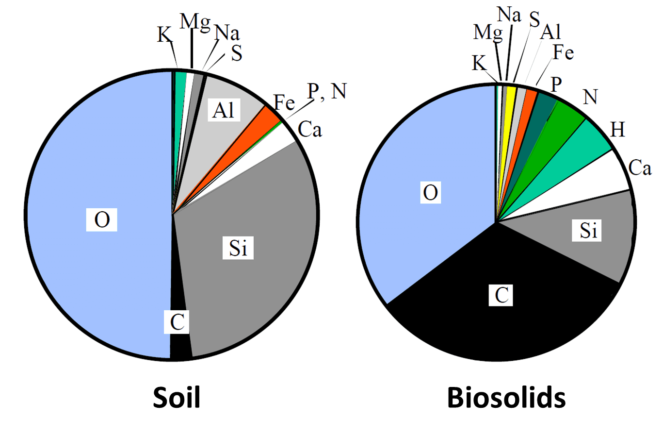
The first thing to know about sewage is that it’s mostly water and only about 250 ppm solids. That is, if you boiled down a pot of sewage, only about 1/40 of 1% of it would remain as solids at the bottom of the pot. There would be some dried poop, some bits of lint and soap, the remains of potato peelings… Mostly, the sewage is water, and mostly it would have boiled away. The second thing to know, is that the solids, the bio-solids, are a lot like soil but better: more valuable, brown gold if used right. While our county mostly burns and landfills the solids remnant of our treated sewage, the wiser choice would be to convert it to fertilizer. Here is a comparison between the composition of soil and bio-solids.

The composition of soil and the composition of bio-solid waste. biosolids are like soil, just better.

The composition of soil and the composition of bio-solid waste. biosolids are like soil, just better.

Most of Oakland’s sewage goes to Detroit where they mostly dry and burn it, and land fill the rest. These processes are expensive and engineering- problematic. It takes a lot of energy to dry these solids to the point where they burn (they’re like really wet wood), and even then they don’t burn nicely. As shown above, the biosolids contain lots of sulfur and that makes combustion smelly. They also contain nitrate, and that makes combustion dangerous. It’s sort of like burning natural gun powder.

The preferred solution is partial combustion (oxidation) at room temperature by bacteria followed by conversion to fertilizer. In Detroit we do this first stage of treatment, the slow partial combustion by bacteria. Consider glucose, a typical carbohydrate,

-HCOH- + O–> CO+ H2O.    ∆G°= -114.6 kcal/mol.

The value of ∆G°, is relevant as a determinate of whether the reaction will proceed. A negative value of ∆G°, as above, indicates that the reaction can progress substantially to completion at standard conditions of 25°C and 1 atm pressure. In a sewage plant, many different carbohydrates are treated by many different bacteria (amoebae, paramnesia, and lactobacilli), and the temperature is slightly cooler than room, about 10-15°C, but this value of ∆G° suggests that near total biological oxidation is possible.

The Detroit plant, like most others, do this biological oxidation treatment using either large stirred tanks, of million gallon volume or so, or in flow reactors with a large fraction of cellular-material returning as recycle. Recycle is needed also in the stirred tank process because of the low solid content. The reaction is approximately first order in oxygen, carbohydrate, and bacteria. Thus a 50% cell recycle more or less doubles the speed of the reaction. Air is typically bubbled through the reactor to provide the oxygen, but in Detroit, pure oxygen is used. About half the organic carbon is oxidized and the remainder is sent to a settling pond. The decant (top) water is sent for “polishing” and dumped in the river, while the goop (the bottom) is currently dried for burning or carted off for landfill. The Holly, MI sewage plant uses a heterogeneous reactors for the oxidation: a trickle bed followed by a rotating disk contractor. These have higher bio-content and thus lower area demands and separation costs, but there is a somewhat higher capital cost.

A major component of bio-solids is nitrogen. Much of this in enters the form of urea, NH2-CO-NH2. In an oxidizing environment, bacteria turns the urea and other nitrogen compounds into nitrate. Consider the reaction the presence of washing soda, Na2CO3. The urea is turned into nitrate, a product suitable for gun powder manufacture. The value of ∆G° is negative, and the reaction is highly favorable.

NH2-CO-NH2 + Na2CO3 + 4 O2 –> 2 Na(NO3) + 2 CO2 + 2 H2O.     ∆G° = -177.5 kcal/mol

The mixture of nitrates and dry bio-solids is highly flammable, and there was recently a fire in the Detroit biosolids dryer. If we wished to make fertilizer, we’d probably want to replace the drier with a further stage of bio-treatment. In Wisconsin, and on a smaller scale in Oakland MI, biosolids are treated by higher temperature (thermophilic) bacteria in the absence of air, that is anaerobically. Anaerobic digestion produces hydrogen and methane, and produces highly useful forms of organic carbon.

2 (-HCOH-) –> COCH4        ∆G° = -33.7 Kcal/mol

3 (-HCOH-) + H2O –> -CH2COOH + CO2 +  2 1/2 H2        ∆G° = -21.9 kcal/mol

In a well-designed plant, the methane is recovered to provide heat to the plant, and sometimes to generate power. In Wisconsin, enough methane is produced to cook the fertilizer to sterilization. The product is called “Milorganite” as much of it comes from Milwaukee and much of the nitrate is bound to organics.

Egg-shaped, anaerobic biosolid digestors.

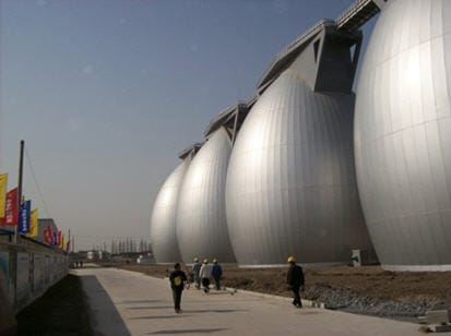
Egg-shaped, anaerobic biosolid digestors, Singapore.

The hydrogen could be recovered too, but typically reacts further within the anaerobic digester. Typically it will reduce the iron oxide in the biosolids from the brown, ferric form, Fe2O3, to black FeO.  In a reducing atmosphere,

Fe2O3 + H2 –> 2 FeO + H2O.

Fe2O3 is the reason leaves turn brown in the fall and is the reason that most poop is brown. FeO is the reason that composted soil is typically black. You’ll notice that swamps are filled with black goo, that’s because of a lack of oxygen at the bottom. Sulphate and phosphorous can be bound to ferrous iron and this is good for fertilizer. Generally you want the reduction reactions to go no further.

Weir dam on the river dour. Used to manage floods, increase residence time, and oxygenate the flow.

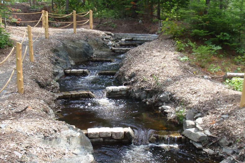
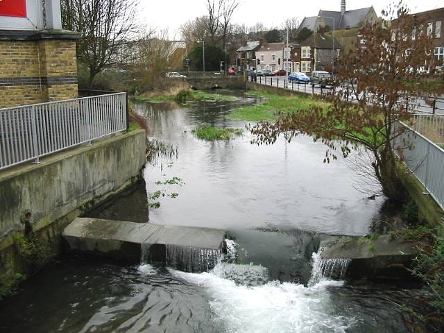
Weir dam on the river Dour in Scotland. Dams of this type increase residence time, and oxygenate the flow. They’re good for fish, pollution, and flooding.

When allowed to continue, the hydrogen produced by anaerobic digestion begins to reduce sulfate to H2S.

NaSO4 + 4.5 H2 –>  NaOH + 3H2O + H2S.

I’m running for Oakland county, MI water commissioner, and one of my aims is to stop wasting our biosolids. Oakland produces nearly 1000,000 pounds of dry biosolids per day. This is either a blessing or a curse depending on how we use it.

Another issue, Oakland county dumps unpasteurized, smelly black goo into Lake St. Clair every other week, whenever it rains more than one inch. I’d like to stop this by separating the storm and “sanitary” sewage. There is a capital cost, but it can save money because we’d no longer have to pay to treat our rainwater at the Detroit sewage plant. To clean the storm runoff, I’d use mini wetlands and weir dams to increase residence time and provide oxygen. Done right, it would look beautiful and would avoid the flash floods. It should also bring natural fish back to the Clinton River.

Robert Buxbaum, May 24 – Sept. 15, 2016 Thermodynamics plays a big role in my posts. You can show that, when the global ∆G is negative, there is an increase in the entropy of the universe.

Of horses, trucks, and horsepower

Horsepower is a unit of work production rate, about 3/4 of a kW, for those who like standard international units. It is also the pulling force of a work horse of the 1700s times its speed when pulling, perhaps 5 mph. A standard truck will develop 200 hp but only while accelerating at about 60 mph; to develop those same 200 horsepower at 1 mph it would have to pull with 200 times more force. That is impossible for a truck, both because of traction limitations and because of the nature of a gasoline engine when attached to typical gearing. At low speed, 1 mph, a truck will barely develop as much force as 4-5 horses, suggesting a work output about 1 hp. This is especially true for a truck pulling in the snow, as shown in the video below.

Here, a semi-truck (of milk) is being pulled out of the snow by a team of horses going perhaps 1 mph. The majority of work is done by the horse on the left — the others seem to be slipping. Assuming that the four horses manage to develop 1 hp each (4 hp total), the pull force is four times a truck at 1 mph, or as great as a 200 hp truck accelerating at 50 mph. That’s why the horse succeed where the truck does not.

You will find other videos on the internet showing that horses produce more force or hp than trucks or tractors. They always do so at low speeds. A horse will also beat a truck or car in acceleration to about the 1/4 mile mark. That’s because acceleration =force /mass: a = F/m.

I should mention that DC electric motors also, like horses, produce their highest force at very low speeds, but unlike horses, their efficiency is very low there. Electric engine efficiency is high only at speeds quite near the maximum and their horse-power output (force times speed) is at a maximum at about 1/2 the maximum speed.

Steam engines (I like steam engines) produce about the same force at all speeds, and more-or-less the same efficiency at all speeds. That efficiency is typically only about 20%, about that of a horse, but the feed cost and maintenance cost is far lower. A steam engine will eat coal, while a horse must eat oats.

March 4, 2016. Robert Buxbaum, an engineer, runs REB Research, and is running for water commissioner.