Some years ago I wrote a largely negative review of Brown’s gas, but the COVID crisis in India makes me want to reconsider. Browns gas can provide a simple source of oxygen for those who are in need. First, an explanation, Browns gas is a two-to-one mix of hydrogen and oxygen; it’s what you get when you do electrolysis of water without any internal separator. Any source of DC electricity will do, e.g. the alternator of a car or a trickle charger of the sort folks buy for their car batteries, and almost any electrode will do too (I’d suggest stainless steel). You can generate pressure just by restricting flow from the electrolysis vessel, and it can be a reasonable source of small-scale oxygen or hydrogen. The reaction is:
H2O –> H2 + 1/2 O2.
The problem with Brown’s gas is that it is explosive, more explosive than hydrogen itself, so you have to handle it with care; avoid sparks until you separate the H2 from the O2. Even the unseparated mix has found some uses, e.g. as a welding gas, or for putting in cars to avoid misfires, increase milage, and decrease pollution. I think that methanol reforming is a better source of automotive hydrogen: hydrogen is a lot safer than this hydrogen-oxygen mix.
Browns gas to oxygen for those who need it.
The mix is a lot less dangerous if you separate the oxygen from the hydrogen with a membrane, as I show in the figure. at right. If you do this it’s a reasonable wy to make oxygen for patients who need oxygen. The electrolysis cell can be a sealed bottle with water and the electrodes; add a flow restriction as shown to create the hydrogen pressure that drives the separation. The power can be an automotive trickle charger. You can get this sort of membranes from REB Research, here and many other suppliers. REB provide consulting services if you like.
In a pinch, you don’t even need the membrane, by the way. You can rely on your lungs to make the separation. A warning, though, the mix is dangerous. Avoid all sparks. Also, don’t put salt into the water. You can can put in some baking soda or lye to speed the electrolysis, but If you put salt in, you’ll find you don’t make oxygen, but will instead make chlorine. And chlorine is deadly. If you’re not sure, smell the gas. If it smells acrid, don’t use it. This is the chlorine-forming reaction.
2NaCl + 2 H2O –> H2 + Cl2 + 2NaOH
Ideally you should vent the hydrogen stream out the window, but for short term, emergency use, the hydrogen can be vented into your home. Don’t do this if anyone smokes (not that anyone should smoke about someone on oxygen). This is a semi-patentable design, but I’m giving it away; not everything that can be patented should be.
Fuel cells are highly efficient and hardly polluting. They have a long history of use in space, and as a power source for submarines. They are beginning to appear powering city buses and intercity trains, at least in Europe, but not so much in the US or Canada. The business case for fuel cells is that they provide clean electric power to the train or bus, without the need for overhead wires. Avoiding wires helps make up for the high cost of hydrogen as a fuel. The reluctance to switch to fuel cells is the US is due to the longer distances that must be covered. The very low volumetric energy density of hydrogen means you need many filling stations with hydrogen fuel cells, and many fill ups per trip.
Energy density CNG, hydrogen, hythane.
On a mass-basis, hydrogen is energy dense, with 1 kg providing the same energy as 2-3 kg of gasoline. The problem with hydrogen (aside from the cost) is that its mass density is very low, less than 50g/liter, even at high pressure. This is terribly un-dense on a volume basis. It would take 20 liters of high pressure hydrogen (about 5 gallons) to take a car or bus as far as with one gallon of gasoline. Even with a huge tank of high pressure hydrogen, 150 gallons or so, a cross country trip would require some 12 fill ups, one every 250 miles, and this is an annoyance, besides being an infrastructure problem.
Then there is cost. In California, hydrogen costs far more than gasoline, between $12 and $15 per kg. That’s ten times as expensive as gasoline on a weight basis and 4 times as expensive on an energy basis. What’s needed is a cheaper, more energy-dense version of hydrogen, ideally one that can be used in both fuel cells and IC engines, and the version I’d like to suggest is hythane, a mix of methane (natural gas) and 20-30% hydrogen.
Hythane dispenser
Hythane has about 3 times the volumetric energy density of hydrogen, and about 1/3 the price. It makes less CO and CO2 pollution because there is far less carbon. On an energy basis, hythane costs just slightly more than gasoline, and requires less infrastructure. Natural gas is cheap and available, delivered by pipeline, without the need for hydrogen delivery trucks. Because hythane has about three times the volumetric energy density of hydrogen, the tank described above, that would give a 250 mile ride with hydrogen, would give 750 miles with hythane. This means a lot fewer fueling stations are needed, and a lot fewer forced stops. As a bonus, hythane can be used in (some) IC engines as well as in fuel cells.
Hydrogen for hythane-automotive use can be made on site, by electrolysis of water. Because there is relatively little hydrogen in the mix, only 25% by volume, or 8% on an energy basis, there is relatively little burden on the electric grid, and fueling will be a lot faster than with battery chargers. Hythane is already in use in buses in China and Canada. These are normal combustion buses but hythane works even better — more efficiently — with fuel cells (solid oxide fuel cells) and thus hythane provides a path to efficiency and greater fuel cell use.
Hythane bus, Montreal.
Natural gas does not work as well in fuel cells; it requires a pre-reformer to make some H2, and even then tends to coke. To be used in most fuel cells, the methane has to be converted, at lest partially into hydrogen and this takes heat energy and water.
CH4 + H2O + energy –> 3H2 + CO
Reforming is a lot easier with hythane; it can be done within the fuel cell. Within a SOFC, the hydrogen combustion, H2 + 1/2 O2 –> H2O, provides heat and water that helps feed the reforming reaction and helps prevent coking. Long term, fuel cells will likely dominate the energy future, but for now it’s nice to have a fuel that will work well in normal IC engines too.
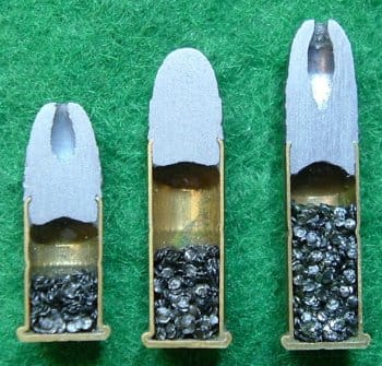
22 long rifle shells contain hardly any propellant.
The most rifle cartridge in the US today is the 22lr a round that first appeared in 1887. It is suitable to small game hunting and while it is less–deadly than larger calibers, data suggests it is effective for personal protection. It is also remarkably low cost. This is because the cartridge in almost entirely empty as shown in the figure at right. It is also incredibly energy efficient, that is to say, it’s incredibly good at transforming heat energy of the powder into mechanical energy in the bullet.
The normal weight of a 22lr is 40 grains, or 2.6 grams; a grain is the weight of a barley grain 1/15.4 gram. Virtually every brand of 22lr will send its bullet at about the speed of sound, 1200 ft/second, with a kinetic energy of about 120 foot pounds, or 162 Joules. This is about twice the energy of a hunting bow, and it will go through a deer. Think of a spike driven by a 120 lb hammer dropped from one foot. That’s the bullet from a typical 22lr.
The explosive combustion heat of several Hodgdon propellants.
The Hodgdon power company is the largest reseller of smokeless powder in the US with products from all major manufacturers, with products selling for an average of $30/lb or .43¢ per grain. The CCI Mini-Mag, shown above, uses 0.8 grains of some powder 0.052 grams, or about 1/3¢ worth, assuming that CCI bought from Hodgdon rather than directly from the manufacturer. You will notice that the energies of the powders hardly varies from type to type, from a low of 3545 J/gram to a high of 4060 J/gram. While I don’t know which powder is used, I will assume CCI uses a high-energy propellant, 4000 J/gram. I now calculate that the heat energy available as 0.052*4000 = 208 Joules. To calculate the efficiency, divide the kinetic energy of the bullet by the 208 Joules. The 40 grain CCI MiniMag bullet has been clocked at 1224 feet per second indicating 130 foot pounds of kinetic energy, or 176 J. Divide by the thermal energy and you find a 85% efficiency: 176J/ 208 J = 85%. That’s far better than your car engine. If the powder were weaker, the efficiency would have to be higher.
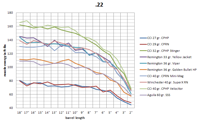
The energy content of various 22lr bullets shot from different length barrels.
I will now calculate the pressure of the gas behind a 22lr. I note that the force on the bullet is equal to the pressure times the cross-sectional area of the barrel. Since energy equals force times distance, we can expect that the kinetic energy gained per inch of barrel equals this force times this distance (1 inch). Because of friction this is an under-estimate of the pressure, but based on the high efficiency, 85%, it’s clear that the pressure can be no more than 15% higher than I will calculate. As it happens, the maximum allowable pressure for 22lr cartridges is set by law at 24,000 psi. When I calculate the actual pressure (below) I find it is about half this maximum.
The change in kinetic energy per inch of barrel is calculated as the change in 1/2 mv2, where m is the mass of the bullet and v is the velocity. There is a web-site with bullet velocity information for many brands of ammunition, “ballistics by the inch”. Data is available for many brands of bullet shot from gun barrels that they cut shorter inch by inch; data for several 22lr are shown here. For the 40 grain CCI MiniMag, they find a velocity of 862 ft/second for 2″ barrel, 965 ft/second for a 3″ barrel, 1043 ft/second for a 4″ barrel, etc. The cross-section area of the barrel is 0.0038 square inches.
Every 22 cartridge has space to spare.
Based on change in kinetic energy, the average pressure in the first two inches of barrel must be 10,845 psi, 5,485 psi in the next inch, and 4,565 psi in the next inch, etc. If I add a 15% correction for friction, I find that the highest pressure is still only half the maximum pressure allowable. Strain gauge deformation data (here) gives a slightly lower value. It appears to me that, by adding more propellant, one could make a legal, higher-performance version of the 22lr — one with perhaps twice the kinetic energy. Given the 1/3¢ cost of powder relative to the 5 to 20¢ price of ammo, I suspect that making a higher power 22lr would be a success.
Robert Buxbaum, March 18, 2021. About 10% of Michigan hunts dear every year during hunting season. Another 20%, as best I can tell own guns for target shooting or personal protection. Just about every lawyer I know carries a gun. They’re afraid people don’t like them. I’m afraid they’re right.
Our company books are done on a Mac mini 2014 that was getting slower and slower for reasons that I mis-diagnosed. I thought it was out of space on the hard drive even though the computer said there was plenty. Then my MacBook started misbehaving too, slowing to a crawl with large web-pages (Facebook) and having trouble backing up. I feared a bug of some sort. Then, 3 weeks ago, the MacBook died. It would not boot up. When I turned it on, it showed a file folder with a question mark. It was dead, but now it’s back thanks to the folks at TechBench on Woodward Ave. I lost some data, but not that much.
As it turns out, the problem was not lack of space on the hard drive, but the hard drive itself. The spinning, magnetic disc that stores my data wore out. I should have seen the problem and replaced the hard drive, but I didn’t realize you could, or should. I replaced the hard drive with a solid state memory bigger than the original, and replaced the battery too. The computer is back, faster than before, and went on to replace the hard drive on the Mini too for good measure. That was 3 weeks ago and everything is working fine.
MacBook hard drive, 120 GB. I replaced it with a solid state stick that had three times the memory and was less than half the size.
I could have bought two new computers, and I have decided to replace the 2011 desktop Mac at work, but I’m happy to have revivified these two machines. A new MacBook would have cost about $1200 while fixing this one cost should have cost $250 — $120 for the hard drive cost and $135 for the fellow who replaced it and recovered as much data as possible. Replacing the battery added another $150 with labor. I saved 2/3 the price of a new MacBook, got more hard disc, and my old programs run faster than before. Fixing up the Mini cost me $250 (no battery), and everything works fine. Because the processor is unchanged, I can still use my legacy programs (Word, pagemaker, photoshop, Quickbooks) and my music.
I’d considered trying to do the same with a 2011 Mini, but Miles at the service center said it was not worth it for a 2011 machine. I have an idea to remove the mechanism and turn this into an external, bootable drive, while transferring the data elsewhere. I’ve done this with old drives before.
In retrospect, I should have made more of an effort to backup data as soon as there was any indication that there was a problems. It was getting slower, and I needed to reboot every other day. As the disc drive wore out, data was being read less and less reliably. Data correction ate up cpu time. The fact is that I forgot I had a spinning disc-drive that could wear out. At least I learned something: hard drives wear out and need replacing. When things break, you might as well learn something. Another thing I learned is about Apple; the computers may cost more than PCs but they last. In the case of my lap book, 2014- 2021 so far.
Robert Buxbaum, March 8, 2021. This isn’t that high tech but it seems useful. As a high tech thought. It strikes me that, just as my laptop battery wore out in 7 years, an electric car battery is also likely to wear out in 7 years. Expect that to be a multi-thousand dollar replacement.
We just got a new toilet. Commonly called a commode, and it’s got a cool feature that I’d seen often in Europe but rarely in the US: two levels of flush strength. There is a “small flush” option that delivers, about 3 liters, intended for yellow waste, and a “big flush” option that delivers 6 liters. It’s intended for brown waste, or poop.
The main advantage of two mode flushing, in my opinion, is that the small flush is quieter than the normal. The quality of the flush is quite acceptable, even for brown waste because the elongated shape of the bowl seems better suited to pushing waste to the back, and down the drain. The flush valve is simple too, and I suspect the valve will last longer than the “flapper valve” of my older, one mode commodes. The secondary advantage is from some cost savings on water. That was about 1¢ per small flush in our area of Michigan, but the water department changed how they charge for water in our area and the cost savings have largely disappeared. Even under the old system, the savings in water cost amounted to only about $15 per year. At that rate it would take 15 years or more to pay for the new commode.
There is no real need for water savings in Michigan, and particularly not in our area, metro-Detroit. In other states there often is, but our drinking water comes from the Detroit river, and the cleaned up waste goes back to the river. It’s a cycle with no water lost no matter how much you flush, and no matter how big shower heads. I’d written in favor of allowing big flush toilets and big shower heads in our state, but the Obama administration ruled otherwise. Trump had promised to change that, but was impeached before he could. Even Trump had changed this, Biden has reversed virtually every Trump order related to resource use including those prohibiting China from providing critical technology to our water and power systems. Bottom line, you have to have a low-flush toilet, and you might as well get a two-mode.
Our commode has an elongated front, and I’d recommend that too. It can minimize floor dribbles, and that’s a good thing. The elongated shape also seems to provide a smoother flush path with less splatter. I would not recommend a “power flush” though for several reasons, among them that you get extra splatter and a louder flush noise. We’d bought a power flush some years ago, and in my opinion, it flushed no better than the ordinary toilet. It was very loud, and had a tendency to splatter. There was some slight water savings, but not worth it, IMHO.
Robert Buxbaum, February 8, 2021. I ran for water commissioner with several goals, among them to improve the fairness of billing, to decrease flooding, and to protect our water system from cyber attack.
Part of the mandate to the 2020 election was to join with Europe and the rest of the western world in agreeing to stop the use of coal. It’s a low cost way to generate energy. Of course we still like to buy things, and we’ve largely turned to China, a country that still burns coal, and thus makes things cheap. The net result of this shift to Chinese goods is that China keeps building coal-fired plants while we shut ours. As it happens, China is worse than the US in terms of CO2 per output, but at least when China pollutes, we don’t see the smoke directly, and we don’t see their new coal plants at all. So we feel better buying things from China than from the US. Besides, slave labor is cheap.
From th eEconomist, December 2020.
Buying Chinese goods is good for the importers, and for the non-manufacturing consumer, at least in the short term. It has the effect of exporting jobs though, and eventually we have to support the displaced workers. It also means we don’t keep up our manufacturing technology. Long term, that affects innovation, and that starts to displace other industries. Antibiotic production has already left the US and along with it semiconductors. Still, we feel good about it since the Chinese don’t let us see the slave labor camps. We do get to see the haze of the pollution.
The Chinese expect this pattern to continue. China is building new coal-fired plants at a furious rate. Presently China has most of the world’s coal-fired power plants. Mostly these are only 4 to 12 years old, far younger than our forty year old plants China plans to build more, and keeps encouraging us to shut down ours. Even 10 years ago, China lead the world in CO2 output. And their fraction of the CO2 keeps climbing.
China is popular with the press. In part, I expect, that’s because they pay the international experts. lAlso, writers and editors are consumers industrial products, but not manufacturers. Consumers benefit from slave labor, or maybe not, but displaced American workers certainly suffer. Also, of course, the news requires pictures and personal stories to keep viewer interest. If you can’t get pictures of young protesters, like Grey Thunberg, you can get an interesting story. Our Chinese pollution is out of sight, and not in the press.
The hope diamond resides in the Smithsonian. It really is a deep blue. It has about 5 ppm boron.
If you’ve ever seen the Hope Dimond, or a picture of it, you’ll notice a most remarkable thing: it is deep blue. While most diamonds are clear, or perhaps grey, a very few are colored. Color in diamonds is generally caused by impurities, in the case of blue diamonds, boron. The Hope diamond has about 5 ppm boron, making it a p-semiconductor. Most blue diamonds, even those just as blue, have less boron. As it turns out one of the major uses of my hydrogen purifiers hydrogen these days is in the manufacture of gem -quality, and semiconductor diamonds, some blue and some other colors. So I thought I’d write about diamonds, colored and not, natural and CVD. It’s interesting and a sort of plug for my company, REB Research.
To start off, natural diamond are formed, over centuries by the effect of high temperature and pressure on a mix of carbon and a natural catalyst mineral, Kimberlite. Diamonds formed this way are generally cubic, relatively clear, and inert, hard, highly heat conductive, and completely non-conducting of electricity. Some man made diamonds are made this way too, using high pressure presses, but gem-quality and semiconductor diamonds are generally made by chemical vapor deposition, CVD. Colored diamonds are made this way too. They have all the properties of clear diamonds, but they have controlled additions and imperfections. Add enough boron, 1000 ppm for example, and the diamond and the resulting blue diamond can conduct electricity fairly readily.
Seeds of natural diamond are placed in a diamond growth chamber and heated to about 1000°C in the presence of ionized, pure methane and hydrogen.
While natural diamond are sometimes used for technical applications, e.g. grind wheels, most technical-use diamonds are man-made by CVD, but the results tend to come out yellow. This was especially true in the early days of manufacture. CVD tends to make large, flat diamonds. This is very useful for heat sinks, and for diamond knives and manufacturers of these were among my first customers. To get a clear color, or to get high-quality colored diamonds, you need a mix of high purity methane and high purity hydrogen, and you need to avoid impurities of silica and the like from the diamond chamber. CVD is also used to make blue-conductive diamonds that can be used as semiconductors or electrodes. The process is show in the gif above from “brilliantearth”.
Multicolored diamonds made by CVD with many different dopants and treatments.
To make a CVD diamond, you place 15 to 30 seed- diamonds into a vacuum growth chamber with a flow of methane and hydrogen in ratio of 1:100 about. You heat the gas to about 1000°C (900-1200°C) , while ionizing the gas using microwaves or a hot wire. The diamonds grow epitaxially over the course of several days or weeks. Ionized hydrogen keeps the surface active, while preventing it from becoming carbonized — turning to graphite. If there isn’t enough hydrogen, you get grey, weak diamonds. If the gas isn’t pure, you get inclusions that make them appear yellow or brown. Nitrogen-impure diamonds are n-semiconductors, with a band gap greater than with boron-blue diamonds, 0.5-1 volts more. Because of this difference, nitrogen-impure diamonds absorb blue or green light, making them appear yellow, while blue diamonds absorb red light, making them blue. (This is different from the reason the sky is blue, explained here.) The difference in energy, also makes yellow diamonds poor electrical conductors. Natural, nitrogen-impure diamonds fluoresce blue or green, as one might expect, but yellow diamonds made by CVD fluoresce at longer wavelengths, reddish (I don’t know why).
The blue moon diamond, it is about as blue as the hope diamond though it has only 0.36 ppm of boron.
To make a higher-quality, yellow, n-type CVD diamonds, use very pure hydrogen. Bright yellow and green color is added by use of ppm-quantities of sulfur or phosphorus. Radiation damage also can be used to add color. Some CVD diamond makers use heat treatment to modify the color and reduce the amount of red fluorescence. CVD pink and purple diamonds are made by hydrogen doping, perhaps followed by heat treatment. The details are proprietary secrets.
Orange-red phosphorescence in the blue moon diamond.
Two major differences help experts distinguish between natural and man-made diamonds. One of these is the fluorescence, Most natural diamonds don’t fluoresce at all, and the ones that do (about 25%) fluoresce blue or green. Almost all CVD diamonds fluoresce orange-red because of nitrogen impurities that absorb blue lights. If you use very pure, nitrogen-free hydrogen, you get clear diamonds avoid much of the fluorescence and yellow. That’s why diamond folks come to us for hydrogen purifiers (and generators). There is a problem with blue diamonds, in that both natural and CVD-absorb and emit red light (that’s why they appear blue). Fortunately for diamond dealers, there is a slight difference in the red emission spectrum between natural and CVD blue diamonds. The natural ones show a mix of red and blue-green. Synthetic diamonds glow only red, typically at 660 nm.
Blue diamonds would be expected to fluoresce red, but instead they show a delayed red fluorescence called phosphorescence. That is to say, when exposed to light, they glow red and continue to glow for 10-30 seconds after the light is turned off. The decay time varies quite a lot, presumably due to differences in the n and p sites.
Natural diamond photographed between polarizers show patterns that radiate from impurities.
Natural and CVD also look different when placed between crossed polarizers. Natural diamonds show multiple direction stress bands, as at left, often radiating from inclusions. CVD diamonds show fine-grained patterns or none at all (they are not made under stress), and man-made, compression diamonds show an X-pattern that matches the press-design, or no pattern at all. If you are interested in hydrogen purifiers, or pure hydrogen generators, for this or any other purposes, please consider REB Research. If you are interested in buying a CVD diamond, there are many for sale, even from deBeers.
Robert Buxbaum, October 19, 2020. The Hope diamond was worn by three French kings, by at least one British king, and by Miss Piggy. A CVD version can be worn by you.
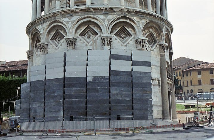
You may know that engineers recently succeed in decreasing the tilt of the “leaning” tower of Pizza by about 1.5°, changing it from about 5.5° to about to precisely 3.98° today –high precision given that the angle varies with the season. But you may not know how that there were at least eight other engineering attempts, and most of these did nothing or made things worse. Neither is it 100% clear that current solution didn’t make things worse. What follows is my effort to learn from the failures and successes, and to speculate on the future. The original-tilted tower is something of an engineering marvel, a highly tilted, stone on stone building that has outlasted earthquakes and weathering that toppled many younger buildings that were built straight vertical, most recently the 1989 collapse of the tower of Pavia. Part of any analysis, must also speak to why this tower survived so long when others failed.
First some basics. The tower of Pisa is an 8 story bell tower for the cathedral next door. It was likely designed by engineer Bonanno Pisano who started construction in 1173. We think it’s Pisano, because he put his name on an inscription on the base, “I, who without doubt have erected this marvelous work that is above all others, am the citizen of Pisa by the name of Bonanno.” Not so humble then, more humble when the tower started to lean, I suspect. The outer diameter at the base is 15.5 m and the weight of the finished tower is 14.7 million kg, 144 million Nt. The pressure exerted on the soil is 0.76 MPa (110 psi). By basic civil engineering, it should stand straight like the walls of the cathedral.
Bonanno’s marvelous work started to sink into the soil of Pisa almost immediately, though. Then it began to tilt. The name Pisa, in Greek, means swamp, and construction, it seems, was not quite on soil, but mud. When construction began the base was likely some 2.5 m (8 feet) above sea level. While a foundation of clay, sand and sea-shells could likely have withstood the weight of the tower, the mud below could not. Pisano added length to the south columns to keep the floors somewhat level, but after three floors were complete, and the tilt continued, he stopped construction. What to do now? What would you do?
If it were me, I’d consider widening the base to distribute the force better, and perhaps add weight to the north side. Instead, Pisano gave up. He completed the third level and went to do other things. The tower stood this way for 99 years, a three-floor, non-functional stub.
About 1272, another engineer, Giovanni di Simone, was charged with fixing the situation. His was the first fix, and it sort-of worked. He strengthened the stonework of the three original floors, widened the base so it wold distribute pressure better, and buried the base too. He then added three more floors. The tower still leaned, but not as fast. De Simone made the south-side columns slightly taller than the north to hide the tilt and allow the floors to be sort-of level. A final two stories were added about 1372, and then the first of the bells. The tower looked as it does today when Gallileo did his famous experiments, dropping balls of different size from the south of the 7th floor between 1589 and 1592.
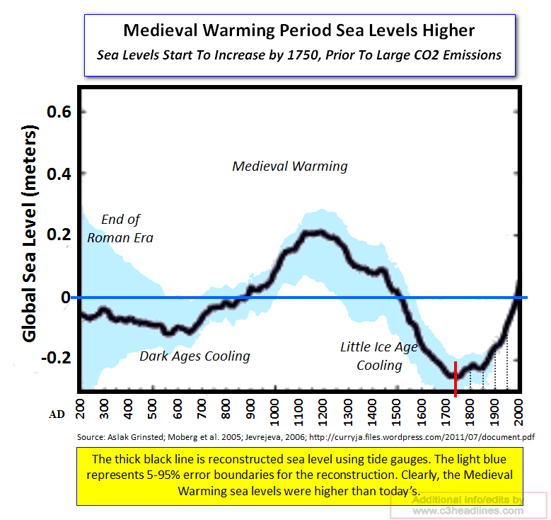
Fortunately for the construction, the world was getting colder and the water table was dropping. While dry soil is stronger than wet, wet soil is more plastic. I suspect it was the wet soil that helped the tower survive earthquakes that toppled other, straight towers. It seems that the tilt not only slowed during this period but briefly reversed, perhaps because of the shift in center of mass, or because of changes in the sea level. Shown below is 1800 years of gauge-based sea-level measurements. Other measures give different sea-level histories, but it seems clear that man-made climate change is not the primary cause. Sea levels would continue to fall till about 1750. By 1820 the tilt had resumed and had reached 4.5°.
The 2nd attempt was begun in 1838. Architect, Alessandro Della Gherardesca got permission to dig around the base at the north to show off the carvings and help right the tower. Unfortunately, the tower base had sunk below the water table. Further, it seems the dirt at the base was helping keep the tower from falling. As Della Gherardesca‘s crew dug, water came spurting out of the ground and the tower tilted another few inches south. The dig was stopped and filled in, but he dig uncovered the Pisano inscription, mentioned above. What would you do now? I might go away, and that’s what was done.
The next attempt to fix the tower (fix 3) was by that self-proclaimed engineering genius, Benito Mussolini. In 1934. Mussolini had his engineers pump some 200 tons of concrete into the south of the tower base hoping to push the tower vertical and stabilize it. The result was that the tower lurched another few inches south. The project was stopped. An engineering lesson: liquids don’t make for good foundations, even when it’s liquid concrete. An unfortunate part of the lesson is that years later engineers would try to fix the tower by pumping water beneath the north end. But that’s getting ahead of myself. Perhaps Mussolini should have made tests on a model before working on the historic tower. Ditto for the more recent version.
On March 18, 1989 the Civic Tower of Pavia started shedding bricks for no obvious reason. This was a vertical tower of the same age and approximate height as the Pisa tower. It collapsed killing four people and injuring 15. No official cause has been reported. I’m going to speculate that the cause was mechanical fatigue and crumbling of the sort that I’ve noticed on the chimney of my own house. Small vibrations of the chimney cause bits of brick to be ejected. If I don’t fix it soon, my chimney will collapse. The wet soils of Pisa may have reduced the vibration damage, or perhaps the stones of Pisa were more elastic. I’ve noticed brick and stone flaking on many prominent buildings, particularly at joins in the chimney.
John Burland’s team cam up with many of the fixes here. They are all science-based, but most of the fixes made things worse.
In 1990, a committee of science and engineering experts was formed to decide upon a fix for the tower of Pisa. It was headed by Professor John Burland, CBE, DSc(Eng), FREng, FRS, NAE, FIC, FCGI. He was, at the time, chair of soil mechanics at the Imperial College, London, and had worked with Ove, Arup, and Partners. He had written many, well regarded articles, and had headed the geological aspects of the design of the Queen Elizabeth II conference center. He was, in a word, an expert, but this tower was different, in part because it was an, already standing, stone-on stone tower that the city wished should remain tilted. The tower was closed to visitors along with all businesses to the south. The bells were removed as well. This was a safety measure, and I don’t count it as a fix. It bought time to decide on a solution. This took two years of deliberation and meetings
In 1992, the committee agreed to fix no 4. The tower was braced with plastic-covered, steel cables that were attached around the second and third floors, with the cables running about 5° from the horizontal to anchor points several hundred meters to the north. The fix was horribly ugly, and messed with traffic. Perhaps the tilt was slowed, it was not stopped.
In 1993, fix number 5. This was the most exciting engineering solution to date: 600 tons of lead ingots were stacked around the base, and water was pumped beneath the north side. This was the reverse of the Mussolini’s failed solution, and the hope was that the tower would tilt north into the now-soggy soil. Unfortunately, the tower tilted further south. One of the columns cracked too, and this attempt was stopped. They were science experts, and it’s not clear why the solution didn’t work. My guess is that they pumped in the water too fast. This is likely the solution I would have proposed, though I hope I would have tested it with a scale model and would have pumped slower. Whatever. Another solution was proposed, this one even more exotic than the last.
For fix number 6, 1995, the team of experts, still overseen by Burland, decided to move the cables and add additional tension. The cables would run straight down from anchors in the base of the north side of the tower to ten underground steel anchors that were to be installed 40 meters below ground level. This would have been an invisible solution, but the anchor depth was well into the water table. So, to anchor the ground anchors, Burland’s team had liquid nitrogen injected into the ground beneath the tower, on the north side where the ground anchors were to go. What Burland did not seem to have realized is that water expands when it freezes, and if you freeze 40 meters of water the length change is significant. On the night of September 7, 1995, the tower lurched southwards by more than it had done in the entire previous year. The team was summoned for an emergency meeting and the liquid nitrogen anchor plan was abandoned.
Tower with the two sets of lead ingots, 900 tons total, about the north side of the base. The weight of the tower is 14,700 tons.
Fix number 7: Another 300 tons of lead ingots were added to the north side as a temporary, simple fix. The fix seems to have worked stabilizing things while another approach was developed.
Fix number 8: In order to allow the removal of the ugly lead bricks another set of engineers were brought on, Roberto Cela and Michele Jamiolkowski. Using helical drills, they had holes drilled at an angle beneath the north side of the tower. Using hoses, they removed a gallon or two of dirt per day for eleven years. The effect of the lead and the dirt removal was to reduce the angle of the tower to 4.5°, the angle that had been measured in 1820. At this point the lead could be removed and tourists were allowed to re-enter. Even after the lead was removed, the angle continued to subside north. It’s now claimed to be 3.98°, and stable. This is remarkable precision for a curved tower whose tilt changes with the seasons.
An engineering joke: How may engineers does it take to change a lightbulb?
Answer 1.04, on average.
The bells in the tower were replaced at this point, and all seemed good, but there was still the worry that the tower would start tilting again. Since water was clearly part of the problem, the British soils expert, Burland came up with fix number 9. He had a series of drainage tunnels built to keep the water from coming back. My worry is that this water removal will leave the tower vulnerable to earthquake and shedding damage, like with the Pavia tower and my chimney. We’ll have to wait for the next earthquake or windstorm to tell for sure. So far, this fix has done no harm.
Robert Buxbaum, October 9, 2020. It’s nice to learn from other folks mistakes, and embarrassments, as well as from their successes. It’s also nice to see how science really works, not with great experts providing the brilliant solution, but slowly, like stumbling in the dark. I see this with COVID-19.
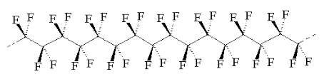
When I was eight or nine year old, I went to the 1963-64 World’s Fair in New York. Among the attractions, in “the kitchen of the future”, I saw the first version of an amazing fry-pan that was coated with plastic. You could cook an egg on that plastic without any oil, and the egg didn’t stick. The plastic was called teflon, a DuPont innovation, whose molecule is shown below.
The molecular structure of Teflon. There is an interior carbon backbone that is completely enclosed with tightly bound fluorine atoms. The net result is a compound that does not bind readily to anything else.
Years later, I came to understand that Teflon’s high-temperature stability and non-stick properties derive from the carbon-fluorine bonds. These bonds are much stronger than the carbon-hydrogen bonds found in food, and most solid, organic things. Because of the strength of the carbon-fluorine bond, Teflon is resistant to oxidation, and to chemical interaction with other molecules, e.g. in food. It does not even interact with water, making it hydrophobic and non-wetting on metals. The carbon-carbon bonds in the middle remained high temperature stable, in part because they were completely shielded by the fluorine atoms.
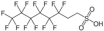
This is a PFAS. The left side is just like teflon, and very hydrophobic. The right side is hydrophilic and highly bonding to pans, and many other things like water or cotton.
But as remarkable as teflon’s non-stick properties are, perhaps the most amazing thing was that it somehow sticks to the pan. For the first generation pans I saw, it didn’t stick very well. Still, the DuPont engineers had found a way to stick non-stick Teflon to a metal for long enough to cook many meals. If they had not found this trick, teflon would not have the majority of its value, but how did they do it? It turns out they used a thin coating of a di-functional compound called PFAS, a a polyfluoro sulphonyl (or polyfluoroalkyl) substance. The molecular structure of a common PFAS, is shown above.
Each molecule of PFAS has one end that’s teflon-like and another end that’s different. The non-Teflon end, in this case a sulfonyl group, is chosen to be both high temperature stable and sticky to metal oxides. The sulphonyl group above is highly polar, and acidic. Acidic will bind to bases, like metal oxides. The surface of the metal pan is prepared by applying a thin layer of oxide or amidine, making it a polar base. The PFAS is then applied, then Teflon. The Teflon-end of the PFAS is bound to teflon by the hydrophobicity of everything else rejecting it.
There are many other uses for PFAS. For example, PFAS is applied to clothing to make it wrinkle free and stain resistant. It can also be used as a super soap, making uncommonly stable foams and bubbles. It is also used in fire-fighting and plane de-icing. Finally, PFAS is the main component of Nafion, the most common membrane for PEM fuel cells. (I can think of yet other applications..) There is just one small problem with PFAS, though. Like teflon, this molecule is uncommonly stable. It doesn’t readily decompose in nature. That would be a small problem if we were sure that PFAS was safe. As it happens it seems safe, but we’re not totally sure.
The safety of PFAS was studied extensively before PFAS-teflon pans was put on the market, but the methodology has been questioned. Large doses of PFAS were fed to test animals, and their health observed. Since the test animals showed no real signs of ill-health though some showed a slight liver enlargement, PFAS was accepted as safe for humans at a lower exposure dose. PFAS was approved for use on pans and allowed to be dumped under conditions where humans would be exposed to 1/1000 of that used on the animals. The assumption was that there would be little or no health hazard at these low exposure levels.
But low risk is not no risk, and today one can sue for even the hint of an effect though use of a class action suit. That is, lawyers sue on behalf of all the people who might have been damaged. My city was sued successfully this way for complicity in sewage over-flows. Of course, since the citizens being paid by the suit are the same ones who have to pay for the damage, only the lawyers benefit. Still, the law is the law, and at least for some judges, putting anyone at risk is enough evidence of willful disregard to hand down a stinging judgement against the evil doer. Judges have begun awarding large claims for PFAS too. While no individual can get the claim more than a tiny amount of money, the lawyers can do very well.
There is no new evidence that PFAS is dangerous, but none is needed if you can get yourself the right judge. In this regard, an industry of judicial tourism has sprung up, where class-action lawyers travel to districts where the judges are favorable. For Teflon suits, the bust hunting grounds are in New York, New Hampshire, and California, and the worst are blood-red states like Wyoming and Utah. Just as different judges promote different precedents, different states allow vastly different PFAS concentrations in the water. A common standard, one used by Michigan, is 70 ppt, 1 billion times stricter than the amounts tested on animals. This is roughly 500 times stricter than the acceptable concentratios for lead, a known poison. The standard in New York is 7 times stricter than Michigan, 10 ppt. The standard in North Carolina is 140,000 ppt, in in several states there is no legal limit to PFAS dumping. There is no scientific logic to all of this, and skeptical view is that the states that rule more strictly for PFAS than lead do so make money for lawyers. Lead is everyone in the natural environment, so you can’t sue as easily for lead. PFAS is a man-made intruder, though, and a strict standard helps lawyers sue. You can find a summary of state by state regulations here.
Any guideline stricter than about 1000 ppt, presents a challenge to the water commissioner who must measure it and enforce the law. There are tricks, though. You can use the surfactant quality of PFAS to concentrate it by a factor of 100 or more. To do this, you take a sample of river water and create bubbles. Any bubbles that form will be highly concentrated in PFAS. Once PFAS can be identified this way, and the concentrators estimated, the polluters can be held liable. Whether we benefit from the strict rulings is another story. If I were making the law for Michigan, I’d probably choose a limit about 1 ppb, but I’m not making the law. The law, as written, may be an idiot, as Bumble said, but the Law is the Law.
In terms of Michigan fishing, while some rivers have PFAS concentrators above the MI-legal limit, they are generally not far over the line. I would trust the fish in the Huron River, even west of Wixom road but I’d suggest you avoid any foam you find floating there. The PFAS content of foam will be much higher than that of the water in general.
Robert E. Buxbaum, June 30, 2020, edited July 8, 2020. There are seven compounds known as PFAS’s: perfluorooctanesulfonic acid (PFOS), perfluorooctanoic acid (PFOA), perfluorononanoic acid (PFNA), perfluorohexanesulfonic acid (PFHxS), perfluoroheptanoic acid (PFHpA), and perfluorobutanesulfonic acid (PFBS).
The rifle Oswald used was a Modello 91/38, Carcano (1938 model of a design originally used in 1891) with an extra-long, 20.9″ barrel, bought for only $19.95 including a 4x sight. That’s $12.50 for the gun, the equivalent of $100 in 2020). The gun may have been cheep, but it was a fine Italian weapon: it was small, fast, pretty, manual, and unreliable. The small size allowed Oswald to get the gun into the book depository without arousing suspicion. He claimed his package held curtain rods, and the small, narrow shape of the gun made the claim believable.
The first question, the fast shooting, is answered in part by the fact that loading the 91/38 Carcano rifle takes practice. Three American marksmen who tried to duplicate the shots for the Warren commission didn’t succeed, but they didn’t have the practice with this type of gun that Oswald had. The Carcano rifle used a bolt and clip loading system that had gone out of style in the US before WWI. To put in a new shell, you manually unlock and pull back the bolt. The old casing then flies out, and the spring–clip loads a new shell. You then have to slam the bolt forward and lock it before you can fire again. For someone practiced, loading this way is faster than with a semi-automatic. To someone without practice it is impossibly slow, like driving a stick shift car for the first time. Even with practice, Americans avoid stick shift cars, but Italians prefer them. Some time after the Warren report came out, Howard Donahue, an American with experience on this type of rifle, was able to hit three moving targets at the distance in 4.8 seconds. That’s less than the shortest estimate of the time it took Oswald to hit twice. Penn of Penn and Teller recreates this on TV, and shows here that Kennedy’s head would indeed have moved backward.
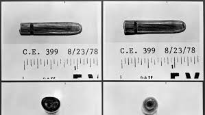
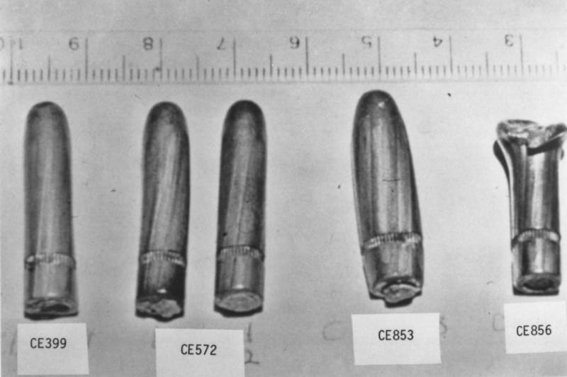
Oswald’s magic bullet, shot two.
That Oswald was so accurate is explained, to great extent by the way the sight was mounted and by the unusual bullets. The model 38 Carcano that Oswald bought fired light, hollow, 6.5×52mm cartridges. This is a 6.5 mm diameter bullet, with a 52 mm long casing. The cartridge was adopted by the Italians in 1940, and dropped by 1941. These bullets are uncommonly bullet is unusually long and narrow (6.5 mm = .26 caliber), round-nosed and hollow from the back to nearly the front. In theory a cartridge like this gives for greater alignment with the barrel., and provides a degree of rocket power acceleration after it leaves the muzzle. Bullets like this were developed in the US, then dropped by the late 1800s. The Italians dropped this bullet for a 7.5 mm diameter version in 1941. The 6.5 mm version can go through two or three people without too much damage, and they can behave erratically. The small diameter and fast speed likely explains how Oswald’s second shot went through Kennedy and Connolly twice without dong much. An American bullet would have done a lot more damage.
Because of the light weight and the extra powder, the 6.5 mm hollow bullet travels uncommonly fast, about 700 m/s at the muzzle with some acceleration afterwards, ideally. Extra powder packs into the hollow part by the force of firing, providing, in theory, low recoil, rocket power. Unfortunately these bullets are structurally weak. They can break apart or bend and going off-direction. By comparison the main US rifle of WWII, the M1, was semi-automatic, with bullets that are shorter, heavier, and slower, going about 585 m/s. Some of our bullets had steel cores too to provide a better combination of penetration and “stopping power”. Only Oswald second shot stayed pristine. It could be that his third shot — the one that made Kennedy’s head explode — flattened or bent in flight.
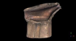
Oswald fragment of third bullet. It’s hollow and seems to have come apart in a way a US bullet would not.
The extra speed of Oswald’s bullets and the alignment of his gun would have given Oswald a great advantage in accuracy. At 100 yards (91 m), test shots with the rifle landed 2 1⁄2 to 5 inches high, within a 3-to-5-inch circle. Good accuracy with a sight that was set to high for close shot accuracy. The funky sight, in my opinion , explains how Oswald managed to miss Walker, but explains how he hit Kennedy accurately especially on the last, longest shot, 81 m to Kennedy’s head
Given the unusually speed of the bullets (I will assume 750 m/s) Oswald’s third shot would have taken 0.108 s to reach the target. If the sight were aligned string and if Kennedy were not moving, the bullet would have been expected to fall 2.24″ low at this range, but given the sight alignment we’d expect him to shoot 3-6″ high on a stationary target, and dead on, on the president in his moving vehicle. Kennedy was moving at 5 m/sand Oswald had a 17° downward shot. The result was a dead on hit to the moving president assuming Oswald didn’t “lead the shot”. The peculiarities of the gun and bullets made Oswald more accurate here than he’d been in the army, while causing him to miss Walker completely at close range.
comparison of the actual, second shot, “magic bullet,” left, with four test-shot bullets. Note that one of the test bullets collapsed, two bent, and one exploded. This is not a reliable bullet design.
We now get to the missed, first shot: How did he miss the car completely firing at the closest range. The answer, might have to do with deformation of the bullets. A hollow base bullet can explode, or got dented and fly off to the side. More prosaically, it could be that he hit a tree branch or a light pole. The Warren commission blamed a tree that was in the way, and there was also a light pole that was never examined. For all we know the bullet is in a branch today, or deflected. US bullets would have a greater chance to barrel on through to at least hit the car. This is an aspect of Italian engineering — when things are light, fast, and flexible, unusual things happen that do not expect to happen with slow, ugly, US products. It’s a price of excellence, Italian style.
Another question appears: Why wasn’t Oswald stopped when the FBI knew he’d threatened Kennedy, and was suspected of shooting at Walker. The simple answer, I think, is that the FBI was slow, and plodding. Beyond this, neither the FBI nor the CIA seem to have worried much about Kennedy’s safety. Even if Kennedy had used the bubble top, Oswald would likely have killed him. Kennedy didn’t care much for the FBI and didn’t trust Texas. Kennedy had a long-running spat with the FBI involving his involvement with organized crime, and perhaps running back to the days when Kennedy’s father was a bootlegger. His relation with the CIA was similar.
The Mateba, Italian semi-automatic revolver, $3000, available only in 357 Magnum and 44 magnum.
I should mention that the engineering styles and attitudes of a country far outlast the particular engineer. We still make big, fat, slow, ugly cars — that are durable and reasonably priced. Germans still overbuild, and Italian cars and guns are as they ever were: beautiful, fast, expensive, and unreliable. The fastest production car is Italian, a Bugatti with a top speed of 245 mph; the fastest rollercoaster is at Ferrari gardens, 149 mph, and in terms of guns, let me suggest you look at the Mateba, left, a $3000 beautiful super fast semi-automatic revolver (really), produced in Italy, and available in 357 magnum and .44 magnum only . It’s a magnificent piece of Italian engineering beautiful, accurate, powerful, and my guess is it’s unreliable as all get out. Our, US pistols typically cost 1/5 to 1/10 as much. A country’s cars, planes, and guns represent the country’s aesthetics. The aesthetics of a county changes only slowly, and I think the world is better off because of it
Robert Buxbaum, February 14, 2020. One of my favorite courses in engineering school, Cooper Union, was in Engineering Aesthetics and design.